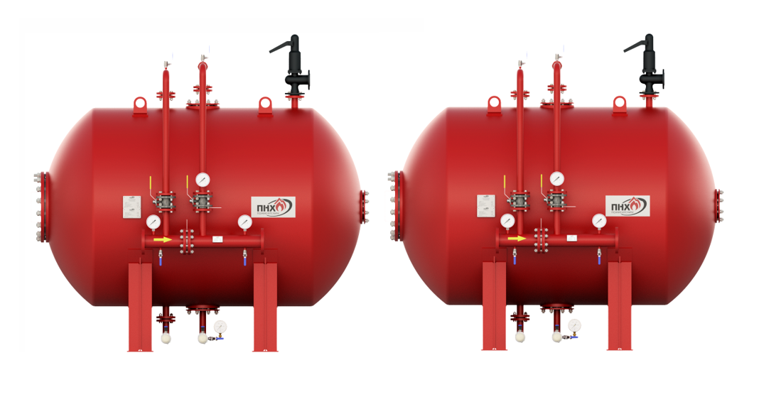
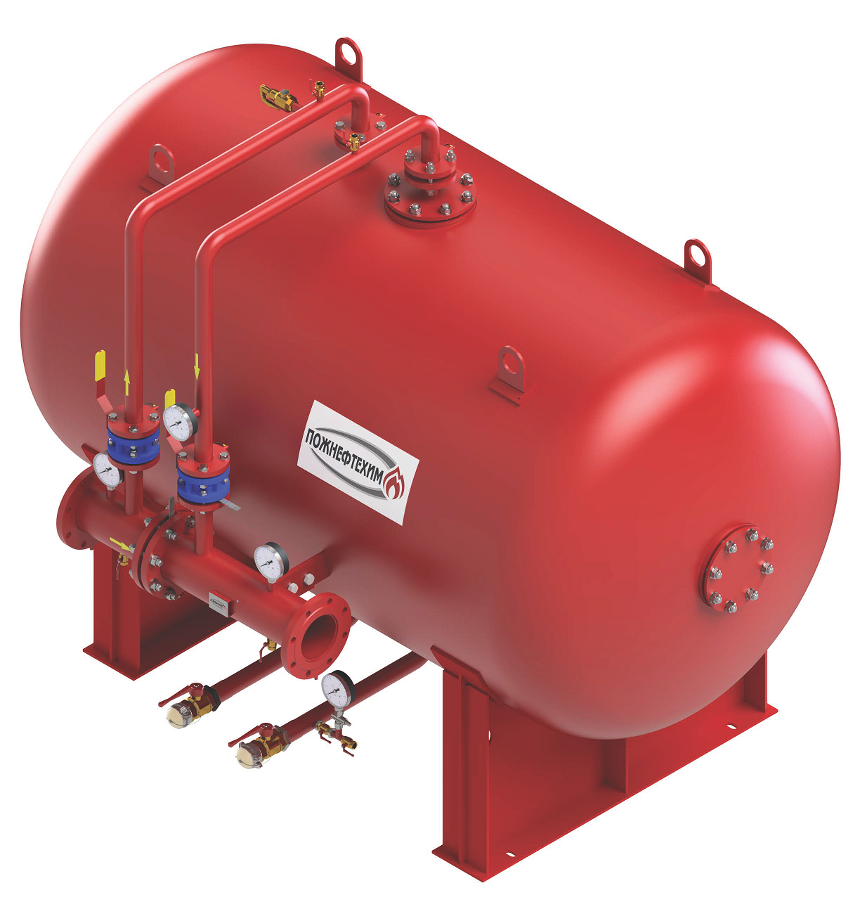
Materials of manufacture
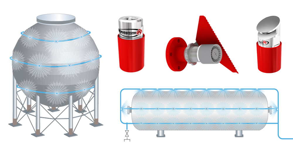
In terms of resistance to climatic effects, the Antifire bladder tanks are manufactured in models U, HL, UHL, T, OM in accordance with GOST 15150-69.
Climatic model U, HL, UHL: material of piping and tank body - steel 09G2S with anti-corrosion coating;
Climatic model T, OM: material of piping and tank body - stainless steel.
Optionally, all types of climatic models of tanks, proportioners and piping can be made of stainless steel.
Key Specifications
Indicator name Indicator value
Design pressure, MPa 1,2 Operating pressure range, MPa 0,6–1,4 Nominal pressure, MPa 1,6 Design pressure, MPa, min 2,4 Operating temperature (without electric heating and insulation), ºС +5 ºС to +35 ºС Service life, years, min 10
Manufacture of customized Antifire bladder tank.2 •s-1 and dynamic viscosity, max 2,5 Pa•s.
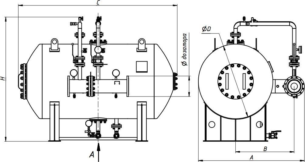
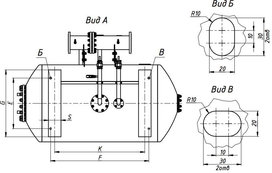
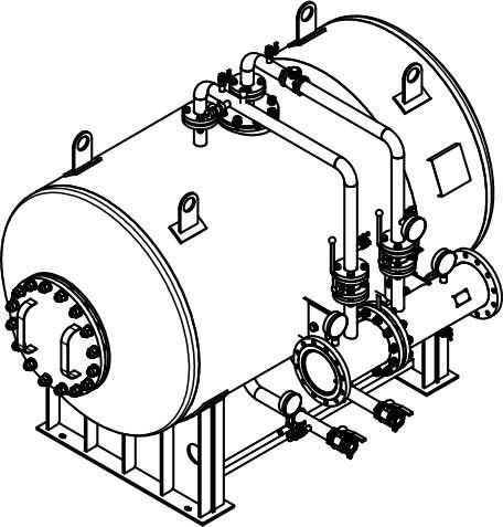
Overall dimensions and weight of the horizontal Antifire bladder tanks
Dimension Drawings Show
Select a proportioner:
---
Select a proportioner
3"
4"
6"
8"
10"
Tank with capacity, V, l :
---
600
1000
1500
2000
2500
3000
3500
4000
4500
5000
5500
6000
6500
7000
7500
8000
8500
9000
9500
10000
10500
11000
11500
12000
12500
13000
13500
14000
14500
15000
15500
16000
16500
17000
Tank with capacity, V, l
600
А, mm
1200
В, mm
700
М, kg
800
Н, mm
1400
С, mm
1500
D, mm
800
Е, mm
500
F, mm
800
G, mm
650
K, mm
700
S, mm
50
Tank with capacity, V, l
1000
А, mm
1350
В, mm
740
М, kg
920
Н, mm
1850
С, mm
1700
D, mm
1000
Е, mm
700
F, mm
800
G, mm
860
К, mm
740
S, mm
170
Tank with capacity, V, l
1500
А, mm
1350
В, mm
740
М, kg
1045
Н, mm
1850
С, mm
2200
D, mm
1000
Е, mm
700
F, mm
1290
G, mm
860
К, mm
1230
S, mm
190
Tank with capacity, V, l
2000
А, mm
1450
В, mm
790
М, kg
1225
Н, mm
1950
С, mm
2550
D, mm
1100
Е, mm
700
F, mm
1490
G, mm
960
К, mm
1400
S, mm
200
Tank with capacity, V, l
2500
А, mm
1560
В, mm
850
М, kg
1340
Н, mm
2050
С, mm
2700
D, mm
1200
Е, mm
700
F, mm
1520
G, mm
1060
К, mm
1430
S, mm
200
Tank with capacity, V, l
3000
А, mm
1730
В, mm
920
М, kg
1435
Н, mm
2250
С, mm
2450
D, mm
1400
Е, mm
700
F, mm
1270
G, mm
1260
К, mm
1180
S, mm
200
Tank with capacity, V, l
3500
А, mm
1730
В, mm
920
М, kg
1550
Н, mm
2250
С, mm
2800
D, mm
1400
Е, mm
700
F, mm
1590
G, mm
1260
К, mm
1500
S, mm
200
Tank with capacity, V, l
4000
А, mm
1730
В, mm
920
М, kg
1660
Н, mm
2250
С, mm
3100
D, mm
1400
Е, mm
700
F, mm
1590
G, mm
1260
К, mm
1500
S, mm
200
Tank with capacity, V, l
4500
А, mm
1900
В, mm
990
М, kg
1800
Н, mm
2500
С, mm
2850
D, mm
1600
Е, mm
1250
F, mm
1490
G, mm
1460
К, mm
1350
S, mm
250
Tank with capacity, V, l
5000
А, mm
1900
В, mm
990
М, kg
1900
Н, mm
2500
С, mm
3100
D, mm
1600
Е, mm
1250
F, mm
1640
G, mm
1460
К, mm
1500
S, mm
250
Tank with capacity, V, l
5500
А, mm
1900
В, mm
990
М, kg
1990
Н, mm
2500
С, mm
3300
D, mm
1600
Е, mm
1250
F, mm
1640
G, mm
1460
К, mm
1500
S, mm
250
Tank with capacity, V, l
6000
А, mm
2070
В, mm
1055
М, kg
2110
Н, mm
2700
С, мм
3050
D, mm
1800
Е, mm
1250
F, mm
1565
G, mm
1660
К, mm
1400
S, mm
280
Tank with capacity, V, l
6500
А, mm
2070
В, mm
1055
М, kg
2200
Н, mm
2700
С, mm
3250
D, mm
1800
Е, mm
1250
F, mm
1665
G, mm
1660
К, mm
1500
S, mm
280
Tank with capacity, V, l
7000
А, mm
2300
В, mm
1180
М, kg
2300
Н, mm
3100
С, mm
2900
D, mm
2000
Е, mm
1250
F, mm
1330
G, mm
1860
К, mm
1140
S, mm
300
Tank with capacity, V, l
7500
А, mm
2300
В, mm
1180
М, kg
2380
Н, mm
3100
С, mm
3050
D, mm
2000
Е, mm
1250
F, mm
1490
G, mm
1860
К, mm
1300
S, mm
300
Tank with capacity, V, l
8000
А, mm
2300
В, mm
1180
М, kg
2460
Н, mm
3100
С, mm
3200
D, mm
2000
Е, mm
1250
F, mm
1550
G, mm
1860
К, mm
1360
S, mm
300
Tank with capacity, V, l
8500
А, mm
2300
В, mm
1180
М, kg
2540
Н, mm
3100
С, mm
3300
D, mm
2000
Е, mm
1250
F, mm
1720
G, mm
1860
К, mm
1530
S, mm
300
Tank with capacity, V, l
9000
А, mm
2300
В, mm
1180
М, kg
2620
Н, mm
3100
С, mm
3500
D, mm
2000
Е, mm
1250
F, mm
1920
G, mm
1860
К, mm
1730
S, mm
300
Tank with capacity, V, l
9500
А, mm
2300
В, mm
1180
М, kg
2700
Н, mm
3100
С, mm
3700
D, mm
2000
Е, mm
1250
F, mm
1890
G, mm
1860
К, mm
1700
S, mm
300
Tank with capacity, V, l
10000
А, mm
2300
В, mm
1180
М, kg
2780
Н, mm
3100
С, mm
3850
D, mm
2000
Е, mm
1250
F, mm
2215
G, mm
1860
К, mm
2000
S, mm
300
Tank with capacity, V, l
10500
А, mm
2300
В, mm
1180
М, kg
2920
Н, mm
3100
С, mm
4000
D, mm
2000
Е, mm
1250
F, mm
2215
G, mm
1860
К, mm
2000
S, mm
310
Tank with capacity, V, l
11000
А, mm
2300
В, mm
1180
М, kg
3060
Н, mm
3100
С, mm
4150
D, mm
2000
Е, mm
1250
F, mm
2215
G, mm
1860
К, mm
2000
S, mm
310
Tank with capacity, V, l
11500
А, mm
2300
В, mm
1180
М, kg
3200
Н, mm
3100
С, mm
4300
D, mm
2000
Е, mm
1250
F, mm
2215
G, mm
1860
К, mm
2000
S, mm
310
Tank with capacity, V, l
12000
А, mm
2300
В, mm
1180
М, kg
3350
Н, mm
3100
С, mm
4500
D, mm
2000
Е, mm
1250
F, mm
2215
G, mm
1860
К, mm
2000
S, mm
310
Tank with capacity, V, l
12500
А, mm
2300
В, mm
1180
М, kg
3490
Н, mm
3100
С, mm
4650
D, mm
2000
Е, mm
1250
F, mm
2215
G, mm
1860
К, mm
2000
S, mm
310
Tank with capacity, V, l
13000
А, mm
2300
В, mm
1180
М, kg
3620
Н, mm
3100
С, mm
4800
D, mm
2000
Е, mm
1250
F, mm
2965
G, mm
1860
К, mm
2750
S, mm
350
Tank with capacity, V, l
13500
А, mm
2300
В, mm
1180
М, kg
3760
Н, mm
3100
С, mm
4950
D, mm
2000
Е, mm
1250
F, mm
3040
G, mm
1860
К, mm
2825
S, mm
350
Tank with capacity, V, l
14000
А, mm
2300
В, mm
1180
М, kg
3900
Н, mm
3100
С, mm
5100
D, mm
2000
Е, mm
1250
F, mm
3125
G, mm
1860
К, mm
2910
S, mm
350
Tank with capacity, V, l
14500
А, mm
2300
В, mm
1180
М, kg
4040
Н, mm
3100
С, mm
5250
D, mm
2000
Е, mm
1250
F, mm
3215
G, mm
1860
К, mm
3000
S, mm
350
Tank with capacity, V, l
15000
А, mm
2300
В, mm
1180
М, kg
4180
Н, mm
3100
С, mm
5400
D, mm
2000
Е, mm
1250
F, mm
3315
G, mm
1860
К, mm
3075
S, mm
350
Tank with capacity, V, l
15500
А, mm
2300
В, mm
1180
М, kg
4320
Н, mm
3100
С, mm
5550
D, mm
2000
Е, mm
1250
F, mm
3130
G, mm
1860
К, mm
2960
S, mm
350
Tank with capacity, V, l
16000
А, mm
2300
В, mm
1180
М, kg
4460
Н, mm
3100
С, mm
5700
D, mm
2000
Е, mm
1250
F, mm
3210
G, mm
1860
К, mm
3040
S, mm
350
Tank with capacity, V, l
16500
А, mm
2300
В, mm
1180
М, kg
4600
Н, mm
3100
С, mm
5850
D, mm
2000
Е, mm
1250
F, mm
3290
G, mm
1860
К, mm
3120
S, mm
350
Tank with capacity, V, l
17000
А, mm
2300
В, mm
1180
М, kg
4890
Н, mm
3100
С, mm
6100
D, mm
2000
Е, mm
1250
F, mm
3370
G, mm
1860
К, mm
3200
S, mm
350
Tank with capacity, V, l
600
1000
1500
2000
2500
3000
3500
4000
4500
5000
5500
6000
6500
7000
7500
8000
8500
9000
9500
10000
10500
11000
11500
12000
12500
13000
13500
14000
14500
15000
15500
16000
16500
17000
Tank with capacity, V, l Antifire bladder tank with 3” proportioner А, mm В, mm M, kg Н, mm С, mm D, mm Е, mm F, mm G, mm К, mm S, mm
600 1200 700 800 1400 1500 800 500 800 650 700 50
1000 1350 740 920 1850 1700 1000 700 800 860 740 170
1500 1350 740 1045 1850 2200 1000 700 1290 860 1230 190
2000 1450 790 1225 1950 2550 1100 700 1490 960 1400 200
2500 1560 850 1340 2050 2700 1200 700 1520 1060 1430 200
3000 1730 920 1435 2250 2450 1400 700 1270 1260 1180 200
3500 1730 920 1550 2250 2800 1400 700 1590 1260 1500 200
4000 1730 920 1660 2250 3100 1400 700 1590 1260 1500 200
4500 1900 990 1800 2500 2850 1600 1250 1490 1460 1350 250
5000 1900 990 1900 2500 3100 1600 1250 1640 1460 1500 250
5500 1900 990 1990 2500 3300 1600 1250 1640 1460 1500 250
6000 2070 1055 2110 2700 3050 1800 1250 1565 1660 1400 280
6500 2070 1055 2200 2700 3250 1800 1250 1665 1660 1500 280
7000 2300 1180 2300 3100 2900 2000 1250 1330 1860 1140 300
7500 2300 1180 2380 3100 3050 2000 1250 1490 1860 1300 300
8000 2300 1180 2460 3100 3200 2000 1250 1550 1860 1360 300
8500 2300 1180 2540 3100 3300 2000 1250 1720 1860 1530 300
9000 2300 1180 2620 3100 3500 2000 1250 1920 1860 1730 300
9500 2300 1180 2700 3100 3700 2000 1250 1890 1860 1700 300
10000 2300 1180 2780 3100 3850 2000 1250 2215 1860 2000 300
10500 2300 1180 2920 3100 4000 2000 1250 2215 1860 2000 310
11000 2300 1180 3060 3100 4150 2000 1250 2215 1860 2000 310
11500 2300 1180 3200 3100 4300 2000 1250 2215 1860 2000 310
12000 2300 1180 3350 3100 4500 2000 1250 2215 1860 2000 310
12500 2300 1180 3490 3100 4650 2000 1250 2215 1860 2000 310
13000 2300 1180 3620 3100 4800 2000 1250 2965 1860 2750 350
13500 2300 1180 3760 3100 4950 2000 1250 3040 1860 2825 350
14000 2300 1180 3900 3100 5100 2000 1250 3125 1860 2910 350
14500 2300 1180 4040 3100 5250 2000 1250 3215 1860 3000 350
15000 2300 1180 4180 3100 5400 2000 1250 3315 1860 3075 350
15500 2300 1180 4320 3100 5550 2000 1250 3130 1860 2960 350
16000 2300 1180 4460 3100 5700 2000 1250 3210 1860 3040 350
16500 2300 1180 4600 3100 5850 2000 1250 3290 1860 3120 350
17000 2300 1180 4890 3100 6100 2000 1250 3370 1860 3200 350
Select a proportioner:
---
600
1000
1500
2000
2500
3000
3500
4000
4500
5000
5500
6000
6500
7000
7500
8000
8500
9000
9500
10000
10500
11000
11500
12000
12500
13000
13500
14000
14500
15000
15500
16000
16500
17000
Tank with capacity, V, l
600
А, mm
1200
В, mm
700
М, kg
810
Н, mm
1400
С, mm
1500
D, mm
800
Е, mm
500
F, mm
800
G, mm
650
K, mm
700
S, mm
50
Tank with capacity, V, l
1000
А, mm
1360
В, mm
740
М, kg
930
Н, mm
1850
С, mm
1700
D, mm
1000
Е, mm
700
F, mm
800
G, mm
860
К, mm
740
S, mm
170
Tank with capacity, V, l
1500
А, mm
1360
В, mm
740
М, kg
1055
Н, mm
1850
С, mm
2200
D, mm
1000
Е, mm
700
F, mm
1290
G, mm
860
К, mm
1230
S, mm
190
Tank with capacity, V, l
2000
А, mm
1460
В, mm
790
М, kg
1235
Н, mm
1950
С, mm
2550
D, mm
1100
Е, mm
700
F, mm
1490
G, mm
960
К, mm
1400
S, mm
200
Tank with capacity, V, l
2500
А, mm
1570
В, mm
850
М, kg
1350
Н, mm
2050
С, mm
2700
D, mm
1200
Е, mm
700
F, mm
1520
G, mm
1060
К, mm
1430
S, mm
200
Tank with capacity, V, l
3000
А, mm
1720
В, mm
900
М, kg
1445
Н, mm
2250
С, mm
2450
D, mm
1400
Е, mm
700
F, mm
1270
G, mm
1260
К, mm
1180
S, mm
200
Tank with capacity, V, l
3500
А, mm
1720
В, mm
900
М, kg
1560
Н, mm
2250
С, mm
2800
D, mm
1400
Е, mm
700
F, mm
1590
G, mm
1260
К, mm
1500
S, mm
200
Tank with capacity, V, l
4000
А, mm
1720
В, mm
900
М, kg
1670
Н, mm
2250
С, mm
3100
D, mm
1400
Е, mm
700
F, mm
1590
G, mm
1260
К, mm
1500
S, mm
200
Tank with capacity, V, l
4500
А, mm
1920
В, mm
1000
М, kg
1810
Н, mm
2500
С, mm
2850
D, mm
1600
Е, mm
1250
F, mm
1490
G, mm
1460
К, mm
1350
S, mm
250
Tank with capacity, V, l
5000
А, mm
1920
В, mm
1000
М, kg
1910
Н, mm
2500
С, mm
3100
D, mm
1600
Е, mm
1250
F, mm
1640
G, mm
1460
К, mm
1500
S, mm
250
Tank with capacity, V, l
5500
А, mm
1920
В, mm
1000
М, kg
2000
Н, mm
2500
С, mm
3300
D, mm
1600
Е, mm
1250
F, mm
1640
G, mm
1460
К, mm
1500
S, mm
250
Tank with capacity, V, l
6000
А, mm
2120
В, mm
1100
М, kg
2120
Н, mm
2700
С, mm
3050
D, mm
1800
Е, mm
1250
F, mm
1565
G, mm
1660
К, mm
1400
S, mm
280
Tank with capacity, V, l
6500
А, mm
2120
В, mm
1100
М, kg
2210
Н, mm
2700
С, mm
3250
D, mm
1800
Е, mm
1250
F, mm
1665
G, mm
1660
К, mm
1500
S, mm
280
Tank with capacity, V, l
7000
А, mm
2320
В, mm
1180
М, kg
2310
Н, mm
3100
С, mm
2900
D, mm
2000
Е, mm
1250
F, mm
1330
G, mm
1860
К, mm
1140
S, mm
300
Tank with capacity, V, l
7500
А, mm
2320
В, mm
1180
М, kg
2390
Н, mm
3100
С, mm
3050
D, mm
2000
Е, mm
1250
F, mm
1490
G, mm
1860
К, mm
1300
S, mm
300
Tank with capacity, V, l
8000
А, mm
2320
В, mm
1180
М, kg
2470
Н, mm
3100
С, mm
3200
D, mm
2000
Е, mm
1250
F, mm
1550
G, mm
1860
К, mm
1360
S, mm
300
Tank with capacity, V, l
8500
А, mm
2320
В, mm
1180
М, kg
2550
Н, mm
3100
С, mm
3300
D, mm
2000
Е, mm
1250
F, mm
1720
G, mm
1860
К, mm
1530
S, mm
300
Tank with capacity, V, l
9000
А, mm
2320
В, mm
1180
М, kg
2630
Н, mm
3100
С, mm
3500
D, mm
2000
Е, mm
1250
F, mm
1920
G, mm
1860
К, mm
1730
S, mm
300
Tank with capacity, V, l
9500
А, mm
2320
В, mm
1180
М, kg
2710
Н, mm
3100
С, mm
3700
D, mm
2000
Е, mm
1250
F, mm
1890
G, mm
1860
К, mm
1700
S, mm
300
Tank with capacity, V, l
10000
А, mm
2320
В, mm
1180
М, kg
2790
Н, mm
3100
С, mm
3850
D, mm
2000
Е, mm
1250
F, mm
2215
G, mm
1860
К, mm
2000
S, mm
300
Tank with capacity, V, l
10500
А, mm
2320
В, mm
1180
М, kg
2930
Н, mm
3100
С, mm
4000
D, mm
2000
Е, mm
1250
F, mm
2215
G, mm
1860
К, mm
2000
S, mm
310
Tank with capacity, V, l
11000
А, mm
2320
В, mm
1180
М, kg
3070
Н, mm
3100
С, mm
4150
D, mm
2000
Е, mm
1250
F, mm
2215
G, mm
1860
К, mm/p>
2000
S, mm
310
Tank with capacity, V, l
11500
А, mm
2320
В, mm
1180
М, kg
3210
Н, mm
3100
С, mm
4300
D, mm
2000
Е, mm
1250
F, mm
2215
G, mm
1860
К, mm
2000
S, mm
310
Tank with capacity, V, l
12000
А, mm
2320
В, mm
1180
М, kg
3360
Н, mm
3100
С, mm
4500
D, mm
2000
Е, mm
1250
F, mm
2215
G, mm
1860
К, mm
2000
S, mm
310
Tank with capacity, V, l
12500
А, mm
2320
В, mm
1180
М, kg
3500
Н, mm
3100
С, mm
4650
D, mm
2000
Е, mm
1250
F, mm
2215
G, mm
1860
К, mm
2000
S, mm
310
Tank with capacity, V, l
13000
А, mm
2320
В, mm
1180
М, kg
3630
Н, mm
3100
С, mm
4800
D, mm
2000
Е, mm
1250
F, mm
2965
G, mm
1860
К, mm
2750
S, mm
350
Tank with capacity, V, l
13500
А, mm
2320
В, mm
1180
М, kg
3770
Н, mm
3100
С, mm
4950
D, mm
2000
Е, mm
1250
F, mm
3040
G, mm
1860
К, mm
2825
S, mm
350
Tank with capacity, V, l
14000
А, mm
2320
В, mm
1180
М, kg
3910
Н, mm
3100
С, mm
5100
D, mm
2000
Е, mm
1250
F, mm
3125
G, mm
1860
К, mm
2910
S, mm
350
Tank with capacity, V, l
14500
А, mm
2320
В, mm
1180
М, kg
4050
Н, mm
3100
С, mm
5250
D, mm
2000
Е, mm
1250
F, mm
3215
G, mm
1860
К, mm
3000
S, mm
350
Tank with capacity, V, l
15000
А, mm
2320
В, mm
1180
М, kg
4190
Н, mm
3100
С,mm
5400
D, mm
2000
Е, mm
1250
F, mm
3315
G, mm
1860
К, mm
3075
S, mm
350
Tank with capacity, V, l
15500
А, mm
2320
В, mm
1180
М, kg
4330
Н, mm
3100
С, mm
5550
D, mm
2000
Е, mm
1250
F, mm
3130
G, mm
1860
К, mm
2960
S, mm
350
Tank with capacity, V, l
16000
А, mm
2320
В, mm
1180
М, kg
4470
Н, mm
3100
С, mm
5700
D, mm
2000
Е, mm
1250
F, mm
3210
G, mm
1860
К, mm
3040
S, mm
350
Tank with capacity, V, l
16500
А, mm
2320
В, mm
1180
М, kg
4610
Н, mm
3100
С, mm
5850
D, mm
2000
Е, mm
1250
F, mm
3290
G, mm
1860
К, mm
3120
S, mm
350
Tank with capacity, V, l
17000
А, mm
2320
В, mm
1180
М, kg
4900
Н, mm
3100
С, mm
6100
D, mm
2000
Е, mm
1250
F, mm
3370
G, mm
1860
К, mm
3200
S, mm
350
Tank with capacity, V, l
600
1000
1500
2000
2500
3000
3500
4000
4500
5000
5500
6000
6500
7000
7500
8000
8500
9000
9500
10000
10500
11000
11500
12000
12500
13000
13500
14000
14500
15000
15500
16000
16500
17000
Tank with capacity, V, l Antifire bladder tank with 4” proportioner А, mm В, mm М, kg Н, mm С, mm D, mm Е, mm F, mm G, mm К, mm S, mm
600 1200 700 810 1400 1500 800 500 800 650 700 50
1000 1360 740 930 1850 1700 1000 700 800 860 740 170
1500 1360 740 1055 1850 2200 1000 700 1290 860 1230 190
2000 1460 790 1235 1950 2550 1100 700 1490 960 1400 200
2500 1570 850 1350 2050 2700 1200 700 1520 1060 1430 200
3000 1720 900 1445 2250 2450 1400 700 1270 1260 1180 200
3500 1720 900 1560 2250 2800 1400 700 1590 1260 1500 200
4000 1720 900 1670 2250 3100 1400 700 1590 1260 1500 200
4500 1920 1000 1810 2500 2850 1600 1250 1490 1460 1350 250
5000 1920 1000 1910 2500 3100 1600 1250 1640 1460 1500 250
5500 1920 1000 2000 2500 3300 1600 1250 1640 1460 1500 250
6000 2120 1100 2120 2700 3050 1800 1250 1565 1660 1400 280
6500 2120 1100 2210 2700 3250 1800 1250 1665 1660 1500 280
7000 2320 1180 2310 3100 2900 2000 1250 1330 1860 1140 300
7500 2320 1180 2390 3100 3050 2000 1250 1490 1860 1300 300
8000 2320 1180 2470 3100 3200 2000 1250 1550 1860 1360 300
8500 2320 1180 2550 3100 3300 2000 1250 1720 1860 1530 300
9000 2320 1180 2630 3100 3500 2000 1250 1920 1860 1730 300
9500 2320 1180 2710 3100 3700 2000 1250 1890 1860 1700 300
10000 2320 1180 2790 3100 3850 2000 1250 2215 1860 2000 300
10500 2320 1180 2930 3100 4000 2000 1250 2215 1860 2000 310
11000 2320 1180 3070 3100 4150 2000 1250 2215 1860 2000 310
11500 2320 1180 3210 3100 4300 2000 1250 2215 1860 2000 310
12000 2320 1180 3360 3100 4500 2000 1250 2215 1860 2000 310
12500 2320 1180 3500 3100 4650 2000 1250 2215 1860 2000 310
13000 2320 1180 3630 3100 4800 2000 1250 2965 1860 2750 350
13500 2320 1180 3770 3100 4950 2000 1250 3040 1860 2825 350
14000 2320 1180 3910 3100 5100 2000 1250 3125 1860 2910 350
14500 2320 1180 4050 3100 5250 2000 1250 3215 1860 3000 350
15000 2320 1180 4190 3100 5400 2000 1250 3315 1860 3075 350
15500 2320 1180 4330 3100 5550 2000 1250 3130 1860 2960 350
16000 2320 1180 4470 3100 5700 2000 1250 3210 1860 3040 350
16500 2320 1180 4610 3100 5850 2000 1250 3290 1860 3120 350
17000 2320 1180 4900 3100 6100 2000 1250 3370 1860 3200 350
Select a proportioner:
---
600
1000
1500
2000
2500
3000
3500
4000
4500
5000
5500
6000
6500
7000
7500
8000
8500
9000
9500
10000
10500
11000
11500
12000
12500
13000
13500
14000
14500
15000
15500
16000
16500
17000
Tank with capacity, V, l
600
А, mm
1250
В, mm
750
М, kg
840
Н, mm
1400
С, mm
1500
D, mm
800
Е, mm
500
F, mm
800
G, mm
650
K, mm
700
S, mm
50
Tank with capacity, V, l
1000
А, mm
1450
В, mm
800
М, kg
960
Н, mm
1850
С, mm
1700
D, mm
1000
Е, mm
700
F, mm
800
G, mm
860
К, mm
740
S, mm
170
Tank with capacity, V, l
1500
А, mm
1450
В, mm
800
М, kg
1080
Н, mm
1850
С, mm
2200
D, mm
1000
Е, mm
700
F, mm
1290
G, mm
860
К, mm
1230
S, mm
190
Tank with capacity, V, l
2000
А, mm
1560
В, mm
860
М, kg
1260
Н, mm
1950
С, mm
2550
D, mm
1100
Е, mm
700
F, mm
1490
G, mm
960
К, mm
1400
S, mm
200
Tank with capacity, V, l
2500
А, mm
1650
В, mm
900
М, kg
1375
Н, mm
2050
С, mm
2700
D, mm
1200
Е, mm
700
F, mm
1520
G, mm
1060
К, mm
1430
S, mm
200
Tank with capacity, V, l
3000
А, mm
1830
В, mm
980
М, kg
1470
Н, mm
2250
С, mm
2450
D, mm
1400
Е, mm
700
F, mm
1270
G, mm
1260
К, mm
1180
S, mm
200
Tank with capacity, V, l
3500
А, mm
1830
В, mm
980
М, kg
1585
Н, mm
2250
С, mm
2800
D, mm
1400
Е, mm
700
F, mm
1590
G, mm
1260
К, mm
1500
S, mm
200
Tank with capacity, V, l
4000
А, mm
1830
В, mm
980
М, kg
1700
Н, mm
2250
С, mm
3100
D, mm
1400
Е, mm
700
F, mm
1590
G, mm
1260
К, mm
1500
S, mm
200
Tank with capacity, V, l
4500
А, mm
2030
В, mm
1075
М, kg
1835
Н, mm
2500
С, mm
2850
D, mm
1600
Е, mm
1250
F, mm
1490
G, mm
1460
К, mm
1350
S, mm
250
Tank with capacity, V, l
5000
А, mm
2030
В, mm
1075
М, kg
1930
Н, mm
2500
С, mm
3100
D, mm
1600
Е, mm
1250
F, mm
1640
G, mm
1460
К, mm
1500
S, mm
250
Tank with capacity, V, l
5500
А, mm
2030
В, mm
1075
М, kg
2025
Н, mm
2500
С, mm
3300
D, mm
1600
Е, mm
1250
F, mm
1640
G, mm
1460
К, mm
1500
S, mm
250
Tank with capacity, V, l
6000
А, mm
2200
В, mm
1150
М, kg
2145
Н, mm
2700
С, mm
3050
D, mm
1800
Е, mm
1250
F, mm
1565
G, mm
1660
К, mm
1400
S, mm
280
Tank with capacity, V, l
6500
А, mm
2200
В, mm
1150
М, kg
2235
Н, mm
2700
С, mm
3250
D, mm
1800
Е, mm
1250
F, mm
1665
G, mm
1660
К, mm
1500
S, mm
280
Tank with capacity, V, l
7000
А, mm
2360
В, mm
1210
М, kg
2335
Н, mm
3100
С, mm
2900
D, mm
2000
Е, mm
1250
F, mm
1330
G, mm
1860
К, mm
1140
S, mm
300
Tank with capacity, V, l
7500
А, mm
2360
В, mm
1210
М, kg
2415
Н, mm
3100
С, mm
3050
D, mm
2000
Е, mm
1250
F, mm
1490
G, mm
1860
К, mm
1300
S, мм
300
Tank with capacity, V, l
8000
А, mm
2360
В, mm
1210
М, kg
2500
Н, mm
3100
С, mm
3200
D, mm
2000
Е, mm
1250
F, mm
1550
G, mm
1860
К, mm
1360
S, mm
300
Tank with capacity, V, l
8500
А, mm
2360
В, mm
1210
М, kg
2580
Н, mm
3100
С, mm
3300
D, mm
2000
Е, mm
1250
F, mm
1720
G, mm
1860
К, mm
1530
S, mm
300
Tank with capacity, V, l
9000
А, mm
2360
В, mm
1210
М, kg
2660
Н, mm
3100
С, mm
3500
D, mm
2000
Е, mm
1250
F, mm
1920
G, mm
1860
К, mm
1730
S,mm
300
Tank with capacity, V, l
9500
А, mm
2360
В, mm
1210
М, kg
2740
Н, mm
3100
С, mm
3700
D, mm
2000
Е, mm
1250
F, mm
1890
G, mm
1860
К, mm
1700
S, mm
300
Tank with capacity, V, l
10000
А, mm
2360
В, mm
1210
М, kg
2820
Н, mm
3100
С, mm
3850
D, mm
2000
Е, mm
1250
F, mm
2215
G, mm
1860
К, mm
2000
S, mm
300
Tank with capacity, V, l
10500
А, mm
2360
В, mm
1210
М, kg
2960
Н, mm
3100
С, mm
4000
D, mm
2000
Е, mm
1250
F, mm
2215
G, mm
1860
К, mm
2000
S, mm
310
Tank with capacity, V, l
11000
А, mm
2360
В, mm
1210
М, kg
3100
Н, mm
3100
С, mm
4150
D, mm
2000
Е, mm
1250
F, mm
2215
G, mm
1860
К, mm
2000
S, mm
310
Tank with capacity, V, l
11500
А, mm
2360
В, mm
1210
М, kg
3240
Н, mm
3100
С, mm
4300
D, mm
2000
Е, mm
1250
F, mm
2215
G, mm
1860
К, mm
2000
S, mm
310
Tank with capacity, V, l
12000
А, mm
2360
В, mm
1210
М, kg
3380
Н, mm
3100
С, mm
4500
D, mm
2000
Е, mm
1250
F, mm
2215
G, mm
1860
К, mm
2000
S, mm
310
Tank with capacity, V, l
12500
А, mm
2360
В, mm
1210
М, kg
3520
Н, mm
3100
С, mm
4650
D, mm
2000
Е, mm
1250
F, mm
2215
G, mm
1860
К, mm
2000
S, mm
310
Tank with capacity, V, l
13000
А, mm
2360
В, mm
1210
М, kg
3660
Н, mm
3100
С, mm
4800
D, mm
2000
Е, mm
1250
F, mm
2965
G, mm
1860
К, mm
2750
S, mm
350
Tank with capacity, V, l
13500
А, mm
2360
В, mm
1210
М, kg
3800
Н, mm
3100
С, mm
4950
D, mm
2000
Е, mm
1250
F, mm
3040
G, mm
1860
К, mm
2825
S, mm
350
Tank with capacity, V, l
14000
А, mm
2360
В, mm
1210
М, kg
3940
Н, mm
3100
С, mm
5100
D, mm
2000
Е, mm
1250
F, mm
3125
G, mm
1860
К, mm
2910
S, mm
350
Tank with capacity, V, l
14500
А, mm
2360
В, mm
1210
М, kg
4080
Н, mm
3100
С, mm
5250
D, mm
2000
Е, mm
1250
F, mm
3215
G, mm
1860
К, mm
3000
S, mm
350
Tank with capacity, V, l
15000
А, mm
2360
В, mm
1210
М, kg
4220
Н, mm
3100
С, mm
5400
D, mm
2000
Е, mm
1250
F, mm
3315
G, mm
1860
К, mm
3075
S, mm
350
Tank with capacity, V, l
15500
А, mm
2360
В, mm
1210
М, kg
4360
Н, mm
3100
С, mm
5550
D, mm
2000
Е, mm
1250
F, mm
3130
G, mm
1860
К, mm
2960
S, mm
350
Tank with capacity, V, l
16000
А, mm
2360
В, mm
1210
М, kg
4500
Н, mm
3100
С, мм
5700
D, mm
2000
Е, mm
1250
F, mm
3210
G, mm
1860
К, mm
3040
S, mm
350
Tank with capacity, V, l
16500
А, mm
2360
В, mm
1210
М, kg
4640
Н, mm
3100
С, mm
5850
D, mm
2000
Е, mm
1250
F, mm
3290
G, mm
1860
К, mm
3120
S, mm
350
Tank with capacity, V, l
17000
А, mm
2360
В, mm
1210
М, kg
4930
Н, mm
3100
С, mm
6100
D, mm
2000
Е, mm
1250
F, mm
3370
G, mm
1860
К, mm
3200
S, mm
350
Tank with capacity, V, l
600
1000
1500
2000
2500
3000
3500
4000
4500
5000
5500
6000
6500
7000
7500
8000
8500
9000
9500
10000
10500
11000
11500
12000
12500
13000
13500
14000
14500
15000
15500
16000
16500
17000
Tank with capacity, V, l БД «Антифайер» с дозирующим устройством 6” А, mm В, mm M, kg Н, mm С, mm D, mm Е, mm F, mm G, mm К, mm S, mm
600 1250 750 840 1400 1500 800 500 800 650 700 50
1000 1450 800 960 1850 1700 1000 700 800 860 740 170
1500 1450 800 1080 1850 2200 1000 700 1290 860 1230 190
2000 1560 860 1260 1950 2550 1100 700 1490 960 1400 200
2500 1650 900 1375 2050 2700 1200 700 1520 1060 1430 200
3000 1830 980 1470 2250 2450 1400 700 1270 1260 1180 200
3500 1830 980 1585 2250 2800 1400 700 1590 1260 1500 200
4000 1830 980 1700 2250 3100 1400 700 1590 1260 1500 200
4500 2030 1075 1835 2500 2850 1600 1250 1490 1460 1350 250
5000 2030 1075 1930 2500 3100 1600 1250 1640 1460 1500 250
5500 2030 1075 2025 2500 3300 1600 1250 1640 1460 1500 250
6000 2200 1150 2145 2700 3050 1800 1250 1565 1660 1400 280
6500 2200 1150 2235 2700 3250 1800 1250 1665 1660 1500 280
7000 2360 1210 2335 3100 2900 2000 1250 1330 1860 1140 300
7500 2360 1210 2415 3100 3050 2000 1250 1490 1860 1300 300
8000 2360 1210 2500 3100 3200 2000 1250 1550 1860 1360 300
8500 2360 1210 2580 3100 3300 2000 1250 1720 1860 1530 300
9000 2360 1210 2660 3100 3500 2000 1250 1920 1860 1730 300
9500 2360 1210 2740 3100 3700 2000 1250 1890 1860 1700 300
10000 2360 1210 2820 3100 3850 2000 1250 2215 1860 2000 300
10500 2360 1210 2960 3100 4000 2000 1250 2215 1860 2000 310
11000 2360 1210 3100 3100 4150 2000 1250 2215 1860 2000 310
11500 2360 1210 3240 3100 4300 2000 1250 2215 1860 2000 310
12000 2360 1210 3380 3100 4500 2000 1250 2215 1860 2000 310
12500 2360 1210 3520 3100 4650 2000 1250 2215 1860 2000 310
13000 2360 1210 3660 3100 4800 2000 1250 2965 1860 2750 350
13500 2360 1210 3800 3100 4950 2000 1250 3040 1860 2825 350
14000 2360 1210 3940 3100 5100 2000 1250 3125 1860 2910 350
14500 2360 1210 4080 3100 5250 2000 1250 3215 1860 3000 350
15000 2360 1210 4220 3100 5400 2000 1250 3315 1860 3075 350
15500 2360 1210 4360 3100 5550 2000 1250 3130 1860 2960 350
16000 2360 1210 4500 3100 5700 2000 1250 3210 1860 3040 350
16500 2360 1210 4640 3100 5850 2000 1250 3290 1860 3120 350
17000 2360 1210 4930 3100 6100 2000 1250 3370 1860 3200 350
Select a proportioner:
---
1000
1500
2000
2500
3000
3500
4000
4500
5000
5500
6000
6500
7000
7500
8000
8500
9000
9500
10000
10500
11000
11500
12000
12500
13000
13500
14000
14500
15000
15500
16000
16500
17000
Tank with capacity, V, l
1000
А, mm
1540
В, mm
860
М, kg
980
Н, mm
1850
С, mm
1700
D, mm
1000
Е, mm
700
F, mm
800
G, mm
860
К, mm
740
S, mm
170
Tank with capacity, V, l
1500
А, mm
1540
В, mm
860
М, kg
1100
Н, mm
1850
С, mm
2200
D, mm
1000
Е, mm
700
F, mm
1290
G, mm
860
К, mm
1230
S, mm
190
Tank with capacity, V, l
2000
А, mm
1640
В, mm
910
М, kg
1285
Н, mm
1950
С, mm
2550
D, mm
1100
Е, mm
700
F, mm
1490
G, mm
960
К, mm
1400
S, mm
200
Tank with capacity, V, l
2500
А, mm
1750
В, mm
960
М, kg
1400
Н, mm
2050
С, mm
2700
D, mm
1200
Е, mm
700
F, мм
1520
G, mm
1060
К, mm
1430
S, mm
200
Tank with capacity, V, l
3000
А, mm
1930
В, mm
1050
М, kg
1500
Н, mm
2250
С, mm
2450
D, mm
1400
Е, mm
700
F, mm
1270
G, mm
1260
К, mm
1180
S, mm
200
Tank with capacity, V, l
3500
А, mm
1930
В, mm
1050
М, kg
1610
Н, mm
2250
С, mm
2800
D, mm
1400
Е, mm
700
F, mm
1590
G, mm
1260
К, mm
1500
S, mm
200
Tank with capacity, V, l
4000
А, mm
1930
В, mm
1050
М, kg
1720
Н, mm
2250
С, mm
3100
D, mm
1400
Е, mm
700
F, mm
1590
G, mm
1260
К, mm
1500
S, mm
200
Tank with capacity, V, l
4500
А, mm
2110
В, mm
1130
М, kg
1860
Н, mm
2500
С, mm
2850
D, mm
1600
Е, mm
1250
F, mm
1490
G, mm
1460
К, mm
1350
S, мм
250
Tank with capacity, V, l
5000
А, mm
2110
В, mm
1130
М, kg
1960
Н, mm
2500
С, mm
3100
D, mm
1600
Е, mm
1250
F, mm
1640
G, mm
1460
К, mm
1500
S, mm
250
Tank with capacity, V, l
5500
А, mm
2110
В, mm
1130
М, kg
2050
Н, mm
2500
С, mm
3300
D, mm
1600
Е, mm
1250
F, mm
1640
G, mm
1460
К, mm
1500
S, mm
250
Tank with capacity, V, l
6000
А, mm
2290
В, mm
1210
М, kg
2170
Н, mm
2700
С, mm
3050
D, mm
1800
Е, mm
1250
F, mm
1565
G, mm
1660
К, mm
1400
S, mm
280
Tank with capacity, V, l
6500
А, mm
2290
В, mm
1210
М, kg
2260
Н, mm
2700
С, mm
3250
D, mm
1800
Е, mm
1250
F, mm
1665
G, mm
1660
К, mm
1500
S, mm
280
Tank with capacity, V, l
7000
А, mm
2430
В, mm
1250
М, kg
2360
Н, mm
3100
С, mm
2900
D, mm
2000
Е, mm
1250
F, mm
1330
G, mm
1860
К, mm
1140
S, mm
300
Tank with capacity, V, l
7500
А, mm
2430
В, mm
1250
М, kg
2440
Н, mm
3100
С, mm
3050
D, mm
2000
Е, mm
1250
F, mm
1490
G, mm
1860
К, mm
1300
S, mm
300
Tank with capacity, V, l
8000
А, mm
2430
В, mm
1250
М, kg
2520
Н, mm
3100
С, mm
3200
D, mm
2000
Е, mm
1250
F, mm
1550
G, mm
1860
К, mm
1360
S, mm
300
Tank with capacity, V, l
8500
А, mm
2430
В, mm
1250
М, kg
2600
Н, mm
3100
С, mm
3300
D, mm
2000
Е, mm
1250
F, mm
1720
G, mm
1860
К, mm
1530
S, mm
300
Tank with capacity, V, l
9000
А, mm
2430
В, mm
1250
М, kg
2680
Н, mm
3100
С, mm
3500
D, mm
2000
Е, mm
1250
F, mm
1920
G, mm
1860
К, mm
1730
S, mm
300
Tank with capacity, V, l
9500
А, mm
2430
В, mm
1250
М, kg
2760
Н, mm
3100
С, mm
3700
D, mm
2000
Е, mm
1250
F, mm
1890
G, mm
1860
К, mm
1700
S, mm
300
Tank with capacity, V, l
10000
А, mm
2430
В, mm
1250
М, kg
2840
Н, mm
3100
С, mm
3850
D, mm
2000
Е, mm
1250
F, mm
2215
G, mm
1860
К, mm
2000
S, mm
300
Tank with capacity, V, l
10500
А, mm
2430
В, mm
1250
М, kg
2980
Н, mm
3100
С, mm
4000
D, mm
2000
Е, mm
1250
F, mm
2215
G, mm
1860
К, mm
2000
S, mm
310
Tank with capacity, V, l
11000
А, mm
2430
В, mm
1250
М, kg
3120
Н, mm
3100
С, mm
4150
D, mm
2000
Е, mm
1250
F, mm
2215
G, mm
1860
К, mm
2000
S, mm
310
Tank with capacity, V, l
11500
А, mm
2430
В, mm
1250
М, kg
3260
Н, mm
3100
С, mm
4300
D, mm
2000
Е, mm
1250
F, mm
2215
G, mm
1860
К, mm
2000
S, mm
310
Tank with capacity, V, l
12000
А, mm
2430
В, mm
1250
М, kg
3400
Н, mm
3100
С, mm
4500
D, mm
2000
Е, mm
1250
F, mm
2215
G, mm
1860
К, mm
2000
S, mm
310
Tank with capacity, V, l
12500
А, mm
2430
В, mm
1250
М, kg
3540
Н, mm
3100
С, mm
4650
D, mm
2000
Е, mm
1250
F, mm
2215
G, mm
1860
К, mm
2000
S, mm
310
Tank with capacity, V, l
13000
А, mm
2430
В, mm
1250
М, kg
3680
Н, mm
3100
С, mm
4800
D, mm
2000
Е, mm
1250
F, mm
2965
G, mm
1860
К, mm
2750
S, mm
350
Tank with capacity, V, l
13500
А, mm
2430
В, mm
1250
М, kg
3820
Н, mm
3100
С, mm
4950
D, mm
2000
Е, mm
1250
F, mm
3040
G, mm
1860
К, mm
2825
S, mm
350
Tank with capacity, V, l
14000
А, mm
2430
В, mm
1250
М, kg
3960
Н, mm
3100
С, mm
5100
D, mm
2000
Е, mm
1250
F, mm
3125
G, mm
1860
К, mm
2910
S, mm
350
Tank with capacity, V, l
14500
А, mm
2430
В, mm
1250
М, kg
4100
Н, mm
3100
С, mm
5250
D, mm
2000
Е, mm
1250
F, mm
3215
G, mm
1860
К, mm
3000
S, mm
350
Tank with capacity, V, l
15000
А, mm
2430
В, mm
1250
М, kg
4240
Н, mm
3100
С, mm
5400
D, mm
2000
Е, mm
1250
F, mm
3315
G, mm
1860
К, mm
3075
S, mm
350
Tank with capacity, V, l
15500
А, mm
2430
В, mm
1250
М, kg
4380
Н, mm
3100
С, mm
5550
D, mm
2000
Е, mm
1250
F, mm
3130
G, mm
1860
К, mm
2960
S, mm
350
Tank with capacity, V, l
16000
А, mm
2430
В, mm
1250
М, kg
4520
Н, mm
3100
С, mm
5700
D, mm
2000
Е, mm
1250
F, mm
3210
G, mm
1860
К, mm
3040
S, mm
350
Tank with capacity, V, l
16500
А, mm
2430
В, mm
1250
М, kg
4660
Н, mm
3100
С, mm
5850
D, mm
2000
Е, mm
1250
F, mm
3290
G, mm
1860
К, mm
3120
S, mm
350
Tank with capacity, V, l
17000
А, mm
2430
В, mm
1250
М, kg
4950
Н, mm
3100
С, mm
6100
D, mm
2000
Е, mm
1250
F, mm
3370
G, mm
1860
К, mm
3200
S, mm
350
Tank with capacity, V, l
1000
1500
2000
2500
3000
3500
4000
4500
5000
5500
6000
6500
7000
7500
8000
8500
9000
9500
10000
10500
11000
11500
12000
12500
13000
13500
14000
14500
15000
15500
16000
16500
17000
Tank with capacity, V, l Antifire bladder tank with 8” proportioner А, mm В, mm M, KG Н, mm С, mm D, mm Е, mm F, mm G, mm К, mm S, mm
1000 1540 860 980 1850 1700 1000 700 800 860 740 170
1500 1540 860 1100 1850 2200 1000 700 1290 860 1230 190
2000 1640 910 1285 1950 2550 1100 700 1490 960 1400 200
2500 1750 960 1400 2050 2700 1200 700 1520 1060 1430 200
3000 1930 1050 1500 2250 2450 1400 700 1270 1260 1180 200
3500 1930 1050 1610 2250 2800 1400 700 1590 1260 1500 200
4000 1930 1050 1720 2250 3100 1400 700 1590 1260 1500 200
4500 2110 1130 1860 2500 2850 1600 1250 1490 1460 1350 250
5000 2110 1130 1960 2500 3100 1600 1250 1640 1460 1500 250
5500 2110 1130 2050 2500 3300 1600 1250 1640 1460 1500 250
6000 2290 1210 2170 2700 3050 1800 1250 1565 1660 1400 280
6500 2290 1210 2260 2700 3250 1800 1250 1665 1660 1500 280
7000 2430 1250 2360 3100 2900 2000 1250 1330 1860 1140 300
7500 2430 1250 2440 3100 3050 2000 1250 1490 1860 1300 300
8000 2430 1250 2520 3100 3200 2000 1250 1550 1860 1360 300
8500 2430 1250 2600 3100 3300 2000 1250 1720 1860 1530 300
9000 2430 1250 2680 3100 3500 2000 1250 1920 1860 1730 300
9500 2430 1250 2760 3100 3700 2000 1250 1890 1860 1700 300
10000 2430 1250 2840 3100 3850 2000 1250 2215 1860 2000 300
10500 2430 1250 2980 3100 4000 2000 1250 2215 1860 2000 310
11000 2430 1250 3120 3100 4150 2000 1250 2215 1860 2000 310
11500 2430 1250 3260 3100 4300 2000 1250 2215 1860 2000 310
12000 2430 1250 3400 3100 4500 2000 1250 2215 1860 2000 310
12500 2430 1250 3540 3100 4650 2000 1250 2215 1860 2000 310
13000 2430 1250 3680 3100 4800 2000 1250 2965 1860 2750 350
13500 2430 1250 3820 3100 4950 2000 1250 3040 1860 2825 350
14000 2430 1250 3960 3100 5100 2000 1250 3125 1860 2910 350
14500 2430 1250 4100 3100 5250 2000 1250 3215 1860 3000 350
15000 2430 1250 4240 3100 5400 2000 1250 3315 1860 3075 350
15500 2430 1250 4380 3100 5550 2000 1250 3130 1860 2960 350
16000 2430 1250 4520 3100 5700 2000 1250 3210 1860 3040 350
16500 2430 1250 4660 3100 5850 2000 1250 3290 1860 3120 350
17000 2430 1250 4950 3100 6100 2000 1250 3370 1860 3200 350
Select a proportioner:
---
1000
1500
2000
2500
3000
3500
4000
4500
5000
5500
6000
6500
7000
7500
8000
8500
9000
9500
10000
10500
11000
11500
12000
12500
13000
13500
14000
14500
15000
15500
16000
16500
17000
Tank with capacity, V, l
1000
А, mm
1600
В, mm
870
М, kg
1050
Н, mm
1850
С, mm
1700
D, mm
1000
Е, mm
700
F, mm
800
G, mm
860
К, mm
740
S, mm
170
Tank with capacity, V, l
1500
А, mm
1600
В, mm
870
М, kg
1180
Н, mm
1850
С, mm
2200
D, mm
1000
Е, mm
700
F, mm
1290
G, mm
860
К, mm
1230
S, mm
190
Tank with capacity, V, l
2000
А, mm
1690
В, mm
910
М, kg
1360
Н, mm
1950
С, mm
2550
D, mm
1100
Е, mm
700
F, mm
1490
G, mm
960
К, mm
1400
S, mm
200
Tank with capacity, V, l
2500
А, mm
1770
В, mm
950
М, kg
1475
Н, mm
2050
С, mm
2700
D, mm
1200
Е, mm
700
F, mm
1520
G, mm
1060
К, mm
1430
S, mm
200
Tank with capacity, V, l
3000
А, mm
1940
В, mm
1020
М, kg
1570
Н, mm
2250
С, mm
2450
D, mm
1400
Е, mm
700
F, mm
1270
G, mm
1260
К, mm
1180
S, mm
200
Tank with capacity, V, l
3500
А, mm
1940
В, mm
1020
М, kg
1685
Н, mm
2250
С, mm
2800
D, mm
1400
Е, mm
700
F, mm
1590
G, mm
1260
К, mm
1500
S, mm
200
Tank with capacity, V, l
4000
А, mm
1940
В, mm
1020
М, kg
1800
Н, mm
2250
С, mm
3100
D, mm
1400
Е, mm
700
F, mm
1590
G, mm
1260
К, mm
1500
S, mm
200
Tank with capacity, V, l
4500
А, mm
2200
В, mm
1150
М, kg
1935
Н, mm
2500
С, mm
2850
D, mm
1600
Е, mm
1250
F, mm
1490
G, mm
1460
К, mm
1350
S, mm
250
Tank with capacity, V, l
5000
А, mm
2200
В, mm
1150
М, kg
2030
Н, mm
2500
С, mm
3100
D, mm
1600
Е, mm
1250
F, mm
1640
G, mm
1460
К, mm
1500
S, mm
250
Tank with capacity, V, l
5500
А, mm
2200
В, mm
1150
М, kg
2125
Н, mm
2500
С, mm
3300
D, mm
1600
Е, mm
1250
F, mm
1640
G, mm
1460
К, mm
1500
S, mm
250
Tank with capacity, V, l
6000
А, mm
2320
В, mm
1200
М, kg
1245
Н, mm
2700
С, mm
3050
D, mm
1800
Е, mm
1250
F, mm
1565
G, mm
1660
К, mm
1400
S, mm
280
Tank with capacity, V, l
6500
А, mm
2320
В, mm
1200
М, kg
2335
Н, mm
2700
С, mm
3250
D, mm
1800
Е, mm
1250
F, mm
1665
G, mm
1660
К, mm
1500
S, mm
280
Tank with capacity, V, l
7000
А, mm
2470
В, mm
1250
М, kg
2435
Н, mm
3100
С, mm
2900
D, mm
2000
Е, mm
1250
F, mm
1330
G, mm
1860
К, mm
1140
S, мм
300
Tank with capacity, V, l
7500
А, mm
2470
В, mm
1250
М, kg
2515
Н, mm
3100
С, mm
3050
D, mm
2000
Е, mm
1250
F, mm
1490
G, mm
1860
К, mm
1300
S, mm
300
Tank with capacity, V, l
8000
А, mm
2470
В, mm
1250
М, kg
2600
Н, mm
3100
С, mm
3200
D, mm
2000
Е, mm
1250
F, mm
1550
G, mm
1860
К, mm
1360
S, mm
300
Tank with capacity, V, l
8500
А, mm
2470
В, mm
1250
М, kg
2680
Н, mm
3100
С, mm
3300
D, mm
2000
Е, mm
1250
F, mm
1720
G, mm
1860
К, mm
1530
S, mm
300
Tank with capacity, V, l
9000
А, mm
2470
В, mm
1250
М, kg
2760
Н, mm
3100
С, mm
3500
D, mm
2000
Е, mm
1250
F, mm
1920
G, mm
1860
К, mm
1730
S, mm
300
Tank with capacity, V, l
9500
А, mm
2470
В, mm
1250
М, kg
2840
Н, mm
3100
С, mm
3700
D, mm
2000
Е, mm
1250
F, mm
1890
G, mm
1860
К, mm
1700
S, mm
300
Tank with capacity, V, l
10000
А, mm
2470
В, mm
1250
М, kg
2920
Н, mm
3100
С, mm
3850
D, mm
2000
Е, mm
1250
F, mm
2215
G, mm
1860
К, mm
2000
S, mm
300
Tank with capacity, V, l
10500
А, mm
2470
В, mm
1250
М, kg
3060
Н, mm
3100
С, mm
4000
D, mm
2000
Е, mm
1250
F, mm
2215
G, mm
1860
К, mm
2000
S, mm
310
Tank with capacity, V, l
11000
А, mm
2470
В, mm
1250
М, kg
3200
Н, mm
3100
С, mm
4150
D, mm
2000
Е, mm
1250
F, mm
2215
G, mm
1860
К, mm
2000
S, mm
310
Tank with capacity, V, l
11500
А, mm
2470
В, mm
1250
М, kg
3340
Н, mm
3100
С, mm
4300
D, mm
2000
Е, mm
1250
F, mm
2215
G, mm
1860
К, mm
2000
S, mm
310
Tank with capacity, V, l
12000
А, mm
2470
В, mm
1250
М, kg
3480
Н, mm
3100
С, mm
4500
D, mm
2000
Е, mm
1250
F, mm
2215
G, mm
1860
К, mm
2000
S, mm
310
Tank with capacity, V, l
12500
А, mm
2470
В, mm
1250
М, kg
3620
Н, mm
3100
С, mm
4650
D, mm
2000
Е, mm
1250
F, mm
2215
G, mm
1860
К, mm
2000
S, mm
310
Tank with capacity, V, l
13000
А, mm
2470
В, mm
1250
М, kg
3760
Н, mm
3100
С, mm
4800
D, mm
2000
Е, mm
1250
F, mm
2965
G, mm
1860
К, mm
2750
S, mm
350
Tank with capacity, V, l
13500
А, mm
2470
В, mm
1250
М, kg
3900
Н, mm
3100
С, mm
4950
D, mm
2000
Е, mm
1250
F, mm
3040
G, mm
1860
К, mm
2825
S, mm
350
Tank with capacity, V, l
14000
А, mm
2470
В, mm
1250
М, kg
4040
Н, mm
3100
С, mm
5100
D, mm
2000
Е, mm
1250
F, mm
3125
G, mm
1860
К, mm
2910
S, mm
350
Tank with capacity, V, l
14500
А, mm
2470
В, mm
1250
М, kg
4180
Н, mm
3100
С, mm
5250
D, mm
2000
Е, mm
1250
F, mm
3215
G, mm
1860
К, mm
3000
S, mm
350
Объём ёмкости, V, л
15000
А, mm
2470
В, mm
1250
М, kg
4320
Н, mm
3100
С, mm
5400
D, mm
2000
Е, mm
1250
F, mm
3315
G, mm
1860
К, mm
3075
S, mm
350
Tank with capacity, V, l
15500
А, mm
2470
В, mm
1250
М, kg
4460
Н, mm
3100
С, mm
5550
D, mm
2000
Е, mm
1250
F, mm
3130
G, mm
1860
К, mm
2960
S, мм
350
Tank with capacity, V, l
16000
А, mm
2470
В, mm
1250
М, kg
4600
Н, mm
3100
С, mm
5700
D, mm
2000
Е, mm
1250
F, mm
3210
G, mm
1860
К, mm
3040
S, mm
350
Tank with capacity, V, l
16500
А, mm
2470
В, mm
1250
М, kg
4740
Н, mm
3100
С, mm
5850
D, mm
2000
Е, mm
1250
F, mm
3290
G, mm
1860
К, mm
3120
S, mm
350
Tank with capacity, V, l
17000
А, mm
2470
В, mm
1250
М, kg
5000
Н, mm
3100
С, mm
6100
D, mm
2000
Е, mm
1250
F, mm
3370
G, mm
1860
К, mm
3200
S, mm
350
Tank with capacity, V, l
1000
1500
2000
2500
3000
3500
4000
4500
5000
5500
6000
6500
7000
7500
8000
8500
9000
9500
10000
10500
11000
11500
12000
12500
13000
13500
14000
14500
15000
15500
16000
16500
17000
Tank with capacity, V, l l Antifire bladder tank with 10” proportioner А, mm В, mm М, kg Н, mm С, mm D, mm Е, mm F, mm G, mm К, mm S, mm
1000 1600 870 1050 1850 1700 1000 700 800 860 740 170
1500 1600 870 1180 1850 2200 1000 700 1290 860 1230 190
2000 1690 910 1360 1950 2550 1100 700 1490 960 1400 200
2500 1770 950 1475 2050 2700 1200 700 1520 1060 1430 200
3000 1940 1020 1570 2250 2450 1400 700 1270 1260 1180 200
3500 1940 1020 1685 2250 2800 1400 700 1590 1260 1500 200
4000 1940 1020 1800 2250 3100 1400 700 1590 1260 1500 200
4500 2200 1150 1935 2500 2850 1600 1250 1490 1460 1350 250
5000 2200 1150 2030 2500 3100 1600 1250 1640 1460 1500 250
5500 2200 1150 2125 2500 3300 1600 1250 1640 1460 1500 250
6000 2320 1200 2245 2700 3050 1800 1250 1565 1660 1400 280
6500 2320 1200 2335 2700 3250 1800 1250 1665 1660 1500 280
7000 2470 1250 2435 3100 2900 2000 1250 1330 1860 1140 300
7500 2470 1250 2515 3100 3050 2000 1250 1490 1860 1300 300
8000 2470 1250 2600 3100 3200 2000 1250 1550 1860 1360 300
8500 2470 1250 2680 3100 3300 2000 1250 1720 1860 1530 300
9000 2470 1250 2760 3100 3500 2000 1250 1920 1860 1730 300
9500 2470 1250 2840 3100 3700 2000 1250 1890 1860 1700 300
10000 2470 1250 2920 3100 3850 2000 1250 2215 1860 2000 300
10500 2470 1250 3060 3100 4000 2000 1250 2215 1860 2000 310
11000 2470 1250 3200 3100 4150 2000 1250 2215 1860 2000 310
11500 2470 1250 3340 3100 4300 2000 1250 2215 1860 2000 310
12000 2470 1250 3480 3100 4500 2000 1250 2215 1860 2000 310
12500 2470 1250 3620 3100 4650 2000 1250 2215 1860 2000 310
13000 2470 1250 3760 3100 4800 2000 1250 2965 1860 2750 350
13500 2470 1250 3900 3100 4950 2000 1250 3040 1860 2825 350
14000 2470 1250 4040 3100 5100 2000 1250 3125 1860 2910 350
14500 2470 1250 4180 3100 5250 2000 1250 3215 1860 3000 350
15000 2470 1250 4320 3100 5400 2000 1250 3315 1860 3075 350
15500 2470 1250 4460 3100 5550 2000 1250 3130 1860 2960 350
16000 2470 1250 4600 3100 5700 2000 1250 3210 1860 3040 350
16500 2470 1250 4740 3100 5850 2000 1250 3290 1860 3120 350
17000 2470 1250 5000 3100 6100 2000 1250 3370 1860 3200 350
Specifications for a diaphragm proportioner (DS)
Select a proportioner:
---
DS-65
DS-80
DS-100
DS-150
DS-200
DS-250
Условный диаметр, мм (дюйм)
65 (2½")
Расход раствора пенообразователя, min-max, л/мин
75-650
Концентрация дозируемого пенообразователя
1 %, 3 %, 6 %
Условный диаметр, мм (дюйм)
80 (3")
Расход раствора пенообразователя, min-max, л/мин
100–900
Концентрация дозируемого пенообразователя
1 %, 3 %, 6 %
Условный диаметр, мм (дюйм)
100 (4")
Расход раствора пенообразователя, min-max, л/мин
250–1800
Концентрация дозируемого пенообразователя
1 %, 3 %, 6 %
Условный диаметр, мм (дюйм)
150 (6")
Расход раствора пенообразователя, min-max, л/мин
450-3500
Концентрация дозируемого пенообразователя
1 %, 3 %, 6 %
Условный диаметр, мм (дюйм)
200 (8")
Расход раствора пенообразователя, min-max, л/мин
1100-8000
Концентрация дозируемого пенообразователя
1 %, 3 %, 6 %
Условный диаметр, мм (дюйм)
250 (10")
Расход раствора пенообразователя, min-max, л/мин
1680-11000
Концентрация дозируемого пенообразователя
1 %, 3 %, 6 %
Indicator name Indicator value DS-65 DS-80 DS-100 DS-150 DS-200 DS-250
Nominal diameter mm (inch) 65 (2½") 80 (3") 100 (4") 150 (6") 200 (8") 250 (10") Foam concentrate solution 75–650 100–900 250–1800 450–3500 1100–8000 1680–11000 Foam concentrate 1 %, 3 %, 6 %
Optionally, proportioners can be manufactured with the insertion range of 0.5% and with other flow rates.
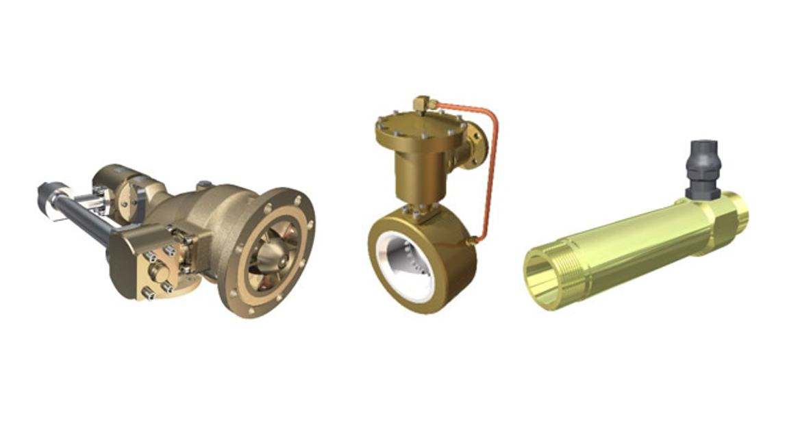
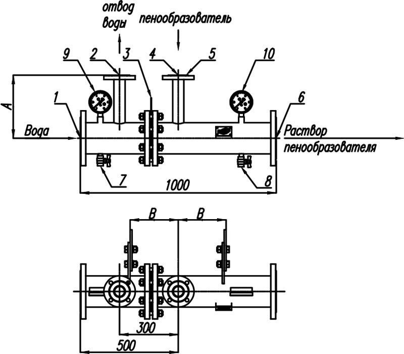
The main elements and overall dimensions of DS proportioners
The main elements of the diaphragm proportioner (DS):
Выберите дозирующее устройство:
---
ДС-65
ДС-80
ДС-100
ДС-150
ДС-200
ДС-250
Размер, мм (дюйм)
65 (2½")
Тип фланцев по ГОСТ 33259-2015 (поз. 1 и 6 на чертеже)
65-16-01-1
Тип фланцев по ГОСТ 33259-2015 (поз. 2 и 4 на чертеже)
50-16-01-1
A, мм
220
B, мм
200
Масса, кг
30
Размер, мм (дюйм)
80 (3")
Тип фланцев по ГОСТ 33259-2015 (поз. 1 и 6 на чертеже)
80-16-01-1
Тип фланцев по ГОСТ 33259-2015 (поз. 2 и 4 на чертеже)
50-16-01-1
A, мм
285
B, мм
215
Масса, кг
40
Размер, мм (дюйм)
100 (4")
Тип фланцев по ГОСТ 33259-2015 (поз. 1 и 6 на чертеже)
100-16-01-1
Тип фланцев по ГОСТ 33259-2015 (поз. 2 и 4 на чертеже)
50-16-01-1
A, мм
295
B, мм
220
Масса, кг
50
Размер, мм (дюйм)
150 (6")
Тип фланцев по ГОСТ 33259-2015 (поз. 1 и 6 на чертеже)
150-16-01-1
Тип фланцев по ГОСТ 33259-2015 (поз. 2 и 4 на чертеже)
50-16-01-1
A, мм
320
B, мм
235
Масса, кг
75
Размер, мм (дюйм)
200 (8")
Тип фланцев по ГОСТ 33259-2015 (поз. 1 и 6 на чертеже)
200-16-01-1
Тип фланцев по ГОСТ 33259-2015 (поз. 2 и 4 на чертеже)
50-16-01-1
A, мм
350
B, мм
240
Масса, кг
100
Размер, мм (дюйм)
250 (10")
Тип фланцев по ГОСТ 33259-2015 (поз. 1 и 6 на чертеже)
250-16-01-1
Тип фланцев по ГОСТ 33259-2015 (поз. 2 и 4 на чертеже)
80-16-01-1
A, мм
380
B, мм
240
Масса, кг
120
Indicator name Indicator value DS-65 DS-80 DS-100 DS-150 DS-200 DS-250
Size, mm (inch) 65 (2½") 80 (3") 100 (4") 150 (6") 200 (8") 250 (10")
Type of flanges in accordance with GOST 33259-2015 65-16-01-1 80-16-01-1 100-16-01-1 150-16-01-1 200-16-01-1 250-16-01-1
Type of flanges in accordance with GOST 33259-2015 50-16-01-1 50-16-01-1 50-16-01-1 50-16-01-1 50-16-01-1 80-16-01-1
A, mm 220 285 295 320 350 380
B, m 200 215 220 235 240 240
Weight, kg 30 40 50 75 100 120
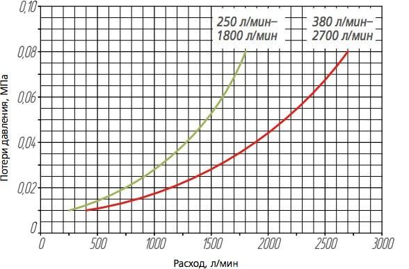
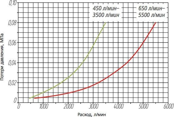
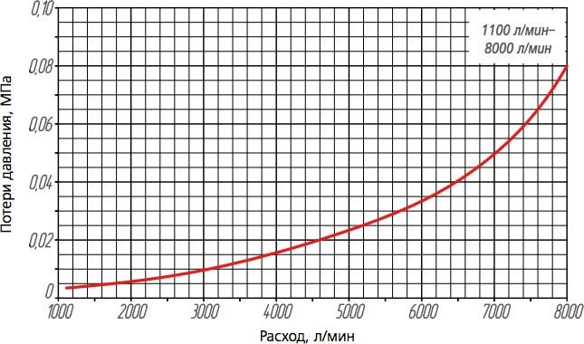
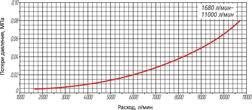
Hydraulic Loss Graphs for DS Proportioners
To compare two graphs, select both values.
Select DS proportioner
---
DS-65
DS-80
DS-100
DS-150
DS-200
DS-250
Select DS proportioner
---
DS-65
DS-80
DS-100
DS-150
DS-200
DS-250
Hydraulic loss graphs for DS-65
Hydraulic loss graphs for DS-80
Hydraulic loss graphs for DS-100
Hydraulic loss graphs for DS-150
Hydraulic loss graphs for DS-200
Hydraulic loss graphs for DS-250
Specifications for a wide range proportioner (DShD)
Выберите дозирующее устройство:
---
ДШД-100
ДШД-150
ДШД-200
ДШД-250
Условный диаметр, мм (дюйм)
100 (4")
Расход раствора пенообразователя, min-max, л/мин
80–2450
Концентрация дозируемого пенообразователя
1 %, 3 %, 6 %
Условный диаметр, мм (дюйм)
150 (6")
Расход раствора пенообразователя, min-max, л/мин
110–5500
Концентрация дозируемого пенообразователя
1 %, 3 %, 6 %
Условный диаметр, мм (дюйм)
200 (8")
Расход раствора пенообразователя, min-max, л/мин
125–10500
Концентрация дозируемого пенообразователя
1 %, 3 %, 6 %
Условный диаметр, мм (дюйм)
250 (10")
Расход раствора пенообразователя, min-max, л/мин
150–16000
Концентрация дозируемого пенообразователя
1 %, 3 %, 6 %
Indicator name Indicator value DShD-100 DShD-150 DShD-200 DShD-250
Nominal diameter, mm (inch) 100 (4") 150 (6") 200 (8") 250 (10") Foam concentrate solution flow rate, 80–2450 110–5500 125–10500 150–16000 Foam concentrate 1 %, 3 %, 6 %
Optionally, proportioners can be manufactured with the insertion rate of 0.5% and with other flow rates.
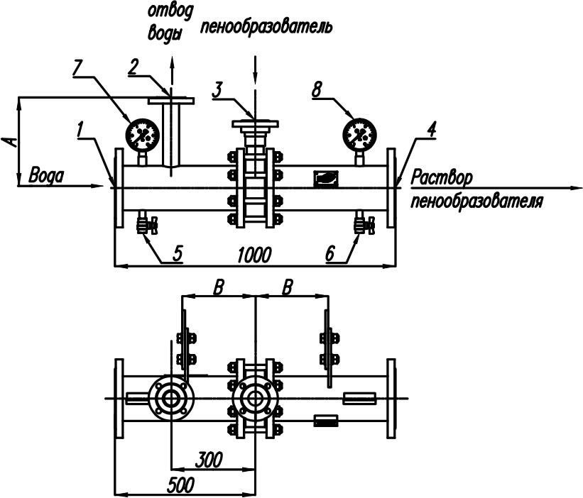
The main elements and overall dimensions of DShD proportioners
1 – flange to feed water from the main line to the proportioner;
Выберите дозирующее устройство:
---
ДШД-100
ДШД-150
ДШД-200
ДШД-250
Размер, мм (дюйм)
100 (4")
Тип фланца по ГОСТ 33259-2015
100-16-01-1
Тип фланца по ГОСТ 33259-2015
50-16-01-1
A, мм
295
B, мм
200
Масса, кг
65
Размер, мм (дюйм)
150 (6")
Тип фланца по ГОСТ 33259-2015
150-16-01-1
Тип фланца по ГОСТ 33259-2015
50-16-01-1
A, мм
320
B, мм
200
Масса, кг
95
Размер, мм (дюйм)
200 (8")
Тип фланца по ГОСТ 33259-2015
200-16-01-1
Тип фланца по ГОСТ 33259-2015
80-16-01-1
A, мм
350
B, мм
210
Масса, кг
140
Размер, мм (дюйм)
250 (10")
Тип фланца по ГОСТ 33259-2015
250-16-01-1
Тип фланца по ГОСТ 33259-2015
80-16-01-1
A, мм
380
B, мм
230
Масса, кг
170
Indicator name Indicator value DShD-100 DShD-150 DShD-200 DShD-250
Size, mm (inch) 100 (4") 150 (6") 200 (8") 250 (10") Type of flanges in accordance with GOST 33259-2015 100-16-01-1 150-16-01-1 200-16-01-1 250-16-01-1 Type of flanges in accordance with GOST 33259-2015 50-16-01-1 50-16-01-1 80-16-01-1 80-16-01-1 A, мм 295 320 350 380 B, мм 200 200 210 230 Масса, кг 65 95 140 170
Hydraulic Loss Graphs for DShD Proportioners
To compare two graphs, select both values.
Select DShD proportioner
---
DShD-100
DShD-150
DShD-200
DShD-250
Select DShD proportioner
---
DShD-100
DShD-150
DShD-200
DShD-250
Hydraulic loss graphs for DShD-100
Hydraulic loss graphs for DShD-150
Hydraulic loss graphs for DShD-200
Hydraulic loss graphs for DShD-250
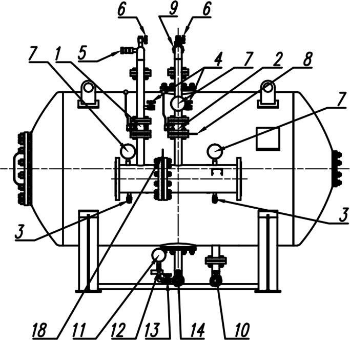
Component parts list for Antifire bladder tank base case
1 – shut-off valve on water feed pipeline to the tank;
Optionally, the product can be supplied with additional equipment.
Для просмотра полного описания технических характеристик отправьте заявку или войдите под своим профилем
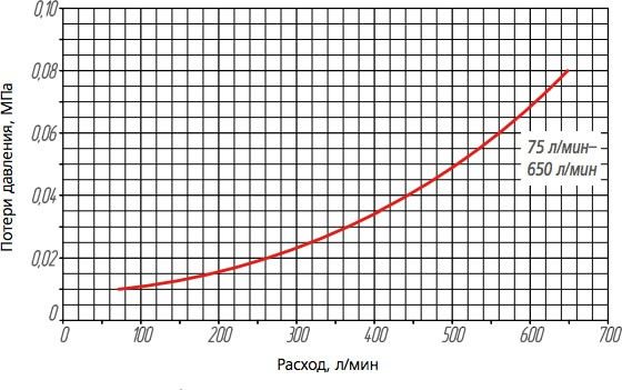 Hydraulic loss graphs for DS-65
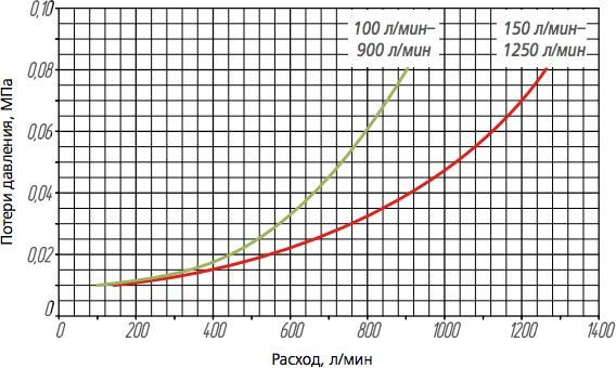 Hydraulic loss graphs for DS-80
 Hydraulic loss graphs for DS-100
 Hydraulic loss graphs for DS-150
 Hydraulic loss graphs for DS-200
 Hydraulic loss graphs for DS-250
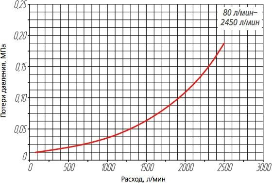 Hydraulic loss graphs for DShD-100
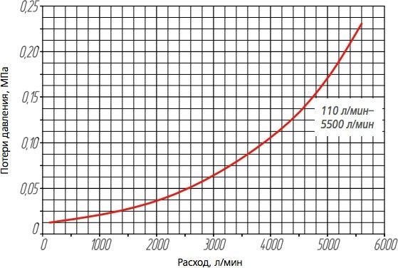 Hydraulic loss graphs for DShD-150
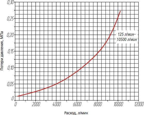 Hydraulic loss graphs for DShD-200
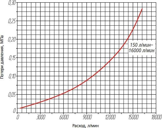 Hydraulic loss graphs for DShD-250