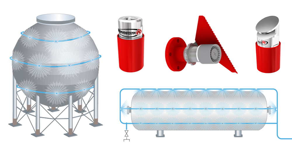
ANTIFIRE DOUBLE VERTICAL BLADDER TANK
TU 4854-016-72410778-2009
General
Purpose and scope
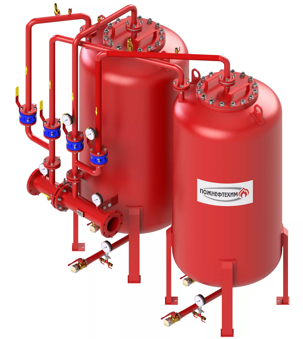
The Antifire bladder tank is a proportioning system designed to inject the foam concentrate stored in the tank into the main line water jet in a percentage ratio corresponding to the type of foam concentrate used. The Antifire bladder tanks can be used in any stationary and mobile foam fire extinguishing installations and are compatible with any water/foam equipment.
The Antifire bladder tank is used in foam fire extinguishing installations of buildings and structures based on the use of sprinkler and deluge sprinklers, foam chambers, high-pressure foam generators, water/foam nozzles, universal generators of low-, medium- and high-expansion foam, combined foam extinguishing installations, etc. Antifire bladder tank can be used with both fresh and sea water.
Antifire bladder tanks are classified:
- by type:
- horizontal;
- vertical;
- double vertical;
- by volume of the container for storing foam concentrate:
- horizontal - 200 to 17000 l;
- vertical - 200 to 12000 l;
- double vertical - 2x200 to 2x12000 l.
Distinctive advantages
- wide range of volumes and operating ranges of flow rate for proportioning;
- internal certified anti-corrosion tank coating;
- manufacture of customized Antifire bladder tank;
- improved technical and operational parameters of the internal flexible container;
- wide range of options (optional equipment with instrumentation and auxiliary equipment).
Design and function
Proportioning in the Antifire bladder tank is carried out by extruding the foam concentrate from the bladder tank into the water jet that passes through a proportioner, along a pipeline through a diaphragm with a calibrated orifice or a control valve. To squeeze the foam concentrate out of the tank we use the pressure of the water coming from the water line to the tank from the outside of the flexible containerand forcing the foam concentrate out of the flexible container into the proportioner under excessive pressure relative to the pressure in the outlet of the proportioner.
Specifications
Materials of manufacture
In terms of resistance to climatic effects, the Antifire bladder tanks are manufactured in models U, HL, UHL, T, OM in accordance with GOST 15150-69.
- Climatic model U, HL, UHL: material of piping and tank body - steel 09G2S with anti-corrosion coating;
- Climatic model T, OM: material of piping and tank body - stainless steel.
Optionally, all types of climatic models of tanks, proportioners and piping can be made of stainless steel.
The DShD is manufactured of brass. On request, another material can be used.
Key Specifications
| Indicator name | Indicator value |
| Design pressure, MPa | 1,2 |
| Operating pressure range, MPa | 0,6–1,4 |
| Nominal pressure, MPa | 1,6 |
| Design pressure, MPa, min | 2,4 |
| Operating temperature (without electric heating and insulation), ºС | +5 ºС to +35 ºС |
| Service life, years, min | 10 |
Manufacture of customized Antifire bladder tank.
The proportioners used as part of the Antifire bladder tank are designed to dispense all types of foam concentrates according to GOST 50588 (including the foam concentrates of the following types: AFFF/AR, FFFP/AR and S/AR with working concentrations of 0.5%, 1%, 3% and 6%), with kinematic viscosity at 20 ºС, max 100 mm2 •s-1 and dynamic viscosity, max 2.5 Pa•s.
Overall dimensions and weight of the double vertical Antifire bladder tanks
Dimension Drawings
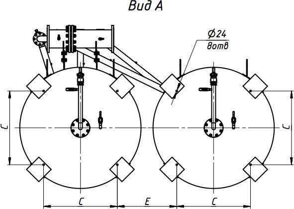
Select a proportioner
Tank with capacity, V, l 600 |
А, mm 1150 |
В, mm 665 |
М, kg 1290 |
C, mm 545 |
D, mm 800 |
H, mm 2200 |
S, mm 1700 |
E, mm 355 |
Tank with capacity, V, l 1000 |
А, mm 1350 |
В, mm 715 |
М, kg 1400 |
C, mm 685 |
D, mm 1000 |
H, mm 2350 |
S, mm 2100 |
E, mm 415 |
Tank with capacity, V, l 1500 |
А, mm 1350 |
В, mm 715 |
М, kg 1680 |
C, mm 685 |
D, mm 1000 |
H, mm 2950 |
S, mm 2100 |
E, mm 415 |
Tank with capacity, V, l 2000 |
А, mm 1450 |
В, mm 750 |
М, kg 2060 |
C, mm 735 |
D, mm 1100 |
H, mm 3200 |
S, mm 2300 |
E, mm 465 |
Tank with capacity, V, l 2500 |
А, mm 1550 |
В, mm 810 |
М, kg 2280 |
C, mm 765 |
D, mm 1200 |
H, mm 3400 |
S, mm 2500 |
E, mm 535 |
Tank with capacity, V, l 3000 |
А, mm 1720 |
В, mm 910 |
М, kg 2460 |
C, mm 905 |
D, mm 1400 |
H, mm 3120 |
S, mm 2900 |
E, mm 600 |
Tank with capacity, V, l 3500 |
А, mm 1720 |
В, mm 910 |
М, kg 2700 |
C, mm 905 |
D, mm 1400 |
H, mm 3450 |
S, mm 2900 |
E, mm 600 |
Tank with capacity, V, l 4000 |
А, mm 1720 |
В, mm 910 |
М, kg 2920 |
C, mm 905 |
D, mm 1400 |
H, mm 3780 |
S, mm 2900 |
E, mm 600 |
Tank with capacity, V, l 4500 |
А, mm 1920 |
В, mm 1010 |
М, kg 3040 |
C, mm 1005 |
D, mm 1600 |
H, mm 3450 |
S, mm 3300 |
E, mm 700 |
Tank with capacity, V, l 5000 |
А, mm 1920 |
В, mm 1010 |
М, kg 3260 |
C, mm 1005 |
D, mm 1600 |
H, mm 3700 |
S, mm 3300 |
E, mm 700 |
Tank with capacity, V, l 5500 |
А, mm 1920 |
В, mm 1010 |
М, kg 3480 |
C, mm 1005 |
D, mm 1600 |
H, mm 3950 |
S, mm 3300 |
E, mm 700 |
Tank with capacity, V, l 6000 |
А, mm 2120 |
В, mm 1110 |
М, kg 3590 |
C, mm 1105 |
D, mm 1800 |
H, mm 3610 |
S, mm 3700 |
E, mm 800 |
Tank with capacity, V, l 6500 |
А, mm 2120 |
В, mm 1110 |
М, kg 3790 |
C, mm 1105 |
D, mm 1800 |
H, mm 3830 |
S, mm 3700 |
E, mm 800 |
Tank with capacity, V, l 7000 |
А, mm 2320 |
В, mm 1210 |
М, kg 3880 |
C, mm 1205 |
D, mm 2000 |
H, mm 3520 |
S, mm 4100 |
E, mm 900 |
Tank with capacity, V, l 7500 |
А, mm 2320 |
В, mm 1210 |
М, kg 4060 |
C, mm 1205 |
D, mm 2000 |
H, mm 3680 |
S, mm 4100 |
E, mm 900 |
Tank with capacity, V, l 8000 |
А, mm 2320 |
В, mm 1210 |
М, kg 4240 |
C, mm 1205 |
D, mm 2000 |
H, mm 3840 |
S, mm 4100 |
E, mm 900 |
Tank with capacity, V, l 8500 |
А, mm 2320 |
В, mm 1210 |
М, kg 4420 |
C, mm 1205 |
D, mm 2000 |
H, mm 4000 |
S, mm 4100 |
E, mm 900 |
Tank with capacity, V, l 9000 |
А, mm 2320 |
В, mm 1210 |
М, kg 4600 |
C, mm 1205 |
D, mm 2000 |
H, mm 4160 |
S, mm 4100 |
E, mm 900 |
Tank with capacity, V, l 9500 |
А, mm 2320 |
В, mm 1210 |
М, kg 4780 |
C, mm 1205 |
D, mm 2000 |
H, mm 4320 |
S, mm 4100 |
E, mm 900 |
Tank with capacity, V, l 10000 |
А, mm 2320 |
В, mm 1210 |
М, kg 4960 |
C, mm 1205 |
D, mm 2000 |
H, mm 4480 |
S, mm 4100 |
E, mm 900 |
Tank with capacity, V, l 10500 |
А, mm 2320 |
В, mm 1210 |
М, kg 5140 |
C, mm 1205 |
D, mm 2000 |
H, mm 4640 |
S, mm 4100 |
E, mm 900 |
Tank with capacity, V, l 11000 |
А, mm 2320 |
В, mm 1210 |
М, kg 5320 |
C, mm 1205 |
D, mm 2000 |
H, mm 4800 |
S, mm 4100 |
E, mm 900 |
Tank with capacity, V, l 11500 |
А, mm 2320 |
В, mm 1210 |
М, kg 5500 |
C, mm 1205 |
D, mm 2000 |
H, mm 4960 |
S, mm 4100 |
E, mm 900 |
Tank with capacity, V, l 12000 |
А, mm 2320 |
В, mm 1210 |
М, kg 5680 |
C, mm 1205 |
D, mm 2000 |
H, mm 5120 |
S, mm 4100 |
E, mm 900 |
Tank with capacity, V, l
| Tank with capacity, V, l | Antifire bladder tank with 3” proportioner | ||||||||||
| А, mm | В, mm | М, kg | C, mm | D, mm | H, mm | S, mm | E, mm | ||||
| 600 | 1150 | 665 | 1290 | 545 | 800 | 2200 | 1700 | 355 | |||
| 1000 | 1350 | 715 | 1400 | 685 | 1000 | 2350 | 2100 | 415 | |||
| 1500 | 1350 | 715 | 1680 | 685 | 1000 | 2950 | 2100 | 415 | |||
| 2000 | 1450 | 750 | 2060 | 735 | 1100 | 3200 | 2300 | 465 | |||
| 2500 | 1550 | 810 | 2280 | 765 | 1200 | 3400 | 2500 | 535 | |||
| 3000 | 1720 | 910 | 2460 | 905 | 1400 | 3120 | 2900 | 600 | |||
| 3500 | 1720 | 910 | 2700 | 905 | 1400 | 3450 | 2900 | 600 | |||
| 4000 | 1720 | 910 | 2920 | 905 | 1400 | 3780 | 2900 | 600 | |||
| 4500 | 1920 | 1010 | 3040 | 1005 | 1600 | 3450 | 3300 | 700 | |||
| 5000 | 1920 | 1010 | 3260 | 1005 | 1600 | 3700 | 3300 | 700 | |||
| 5500 | 1920 | 1010 | 3480 | 1005 | 1600 | 3950 | 3300 | 700 | |||
| 6000 | 2120 | 1110 | 3590 | 1105 | 1800 | 3610 | 3700 | 800 | |||
| 6500 | 2120 | 1110 | 3790 | 1105 | 1800 | 3830 | 3700 | 800 | |||
| 7000 | 2320 | 1210 | 3880 | 1205 | 2000 | 3520 | 4100 | 900 | |||
| 7500 | 2320 | 1210 | 4060 | 1205 | 2000 | 3680 | 4100 | 900 | |||
| 8000 | 2320 | 1210 | 4240 | 1205 | 2000 | 3840 | 4100 | 900 | |||
| 8500 | 2320 | 1210 | 4420 | 1205 | 2000 | 4000 | 4100 | 900 | |||
| 9000 | 2320 | 1210 | 4600 | 1205 | 2000 | 4160 | 4100 | 900 | |||
| 9500 | 2320 | 1210 | 4780 | 1205 | 2000 | 4320 | 4100 | 900 | |||
| 10000 | 2320 | 1210 | 4960 | 1205 | 2000 | 4480 | 4100 | 900 | |||
| 10500 | 2320 | 1210 | 5140 | 1205 | 2000 | 4640 | 4100 | 900 | |||
| 11000 | 2320 | 1210 | 5320 | 1205 | 2000 | 4800 | 4100 | 900 | |||
| 11500 | 2320 | 1210 | 5500 | 1205 | 2000 | 4960 | 4100 | 900 | |||
| 12000 | 2320 | 1210 | 5680 | 1205 | 2000 | 5120 | 4100 | 900 | |||
Specifications for a diaphragm proportioner (DS)
Nominal diameter mm (inch) 65 (2½") |
Foam concentrate solution flow rate, min-max,, l/min 75-650 |
Proportioning ratio 1 %, 3 %, 6 % |
Nominal diameter mm (inch) 80 (3") |
Foam concentrate solution flow rate, min-max,, l/min 100–900 |
Proportioning ratio 1 %, 3 %, 6 % |
Nominal diameter mm (inch) 100 (4") |
Foam concentrate solution flow rate, min-max,, l/min 250–1800 |
Proportioning ratio 1 %, 3 %, 6 % |
Nominal diameter mm (inch) 150 (6") |
Foam concentrate solution flow rate, min-max,, l/min 450-3500 |
Концентрация дозируемого пенообразователя 1 %, 3 %, 6 % |
Nominal diameter mm (inch) 200 (8") |
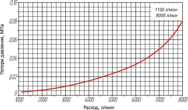
Foam concentrate solution flow rate, min-max,, l/min 1100-8000 |
Proportioning ratio 1 %, 3 %, 6 % |
Nominal diameter mm (inch)) 250 (10") |
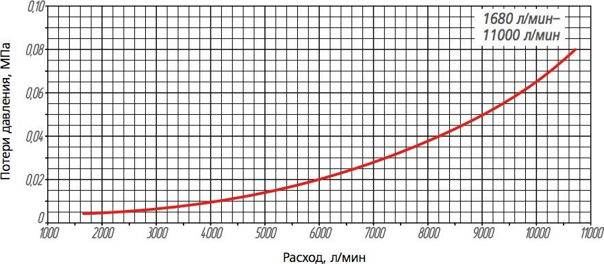
Foam concentrate solution flow rate, min-max,, l/min 1680-11000 |
Proportioning ratio 1 %, 3 %, 6 % |
| Indicator name | Indicator value | |||||
| DS-65 | DS-80 | DS-100 | DS-150 | DS-200 | DS-250 | |
| Nominal diameter mm (inch) | 65 (2½") | 80 (3") | 100 (4") | 150 (6") | 200 (8") | 250 (10") |
| Foam concentrate solution flow rate, min-max, l/min | 75–650 | 100–900 150–1250 | 250–1800 380–2700 | 450–3500 650–5500 | 1100–8000 | 1680–11000 |
| Foam concentrate Proportioning ratio | 1 %, 3 %, 6 % | |||||
Optionally, proportioners can be manufactured with the insertion range of 0.5% and with other flow rates.
The main elements and overall dimensions of DS proportioners
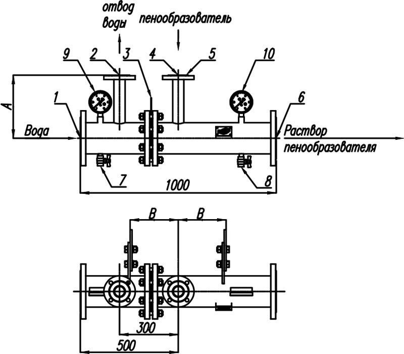
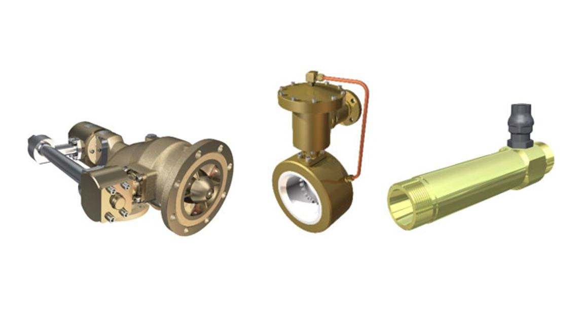
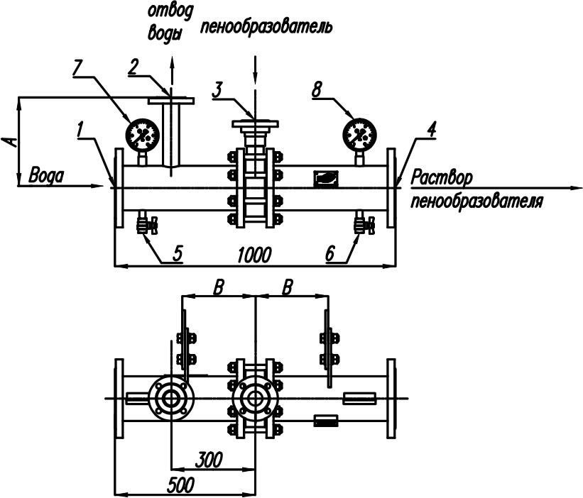
The main elements of the diaphragm proportioner (DS):
1 – flange to feed water fr om the fire extinguishing installation pipeline to proportioner;
2 – flange to drain water to the foam concentrate tank;
3 – diaphragm with a calibrated orifice;
4 – flange to feed foam concentrate fr om the tank to the proportioner;
5 – mount place for the diaphragm with a calibrated orifice;
6 – flange to drain foam concentrate solution fr om the proportioner;
7 and 8 – drain valves;
9 and 10 – pressure gauges.
Size, mm (inch) 65 (2½") |
Type of flanges in accordance with GOST 33259-2015 (pos. 1 and 6 on figure) 65-16-01-1 |
Type of flanges in accordance with GOST 33259-2015 (pos. 2 and 4 on figure) 50-16-01-1 |
A, mm 220 |
B, mm 200 |
Weight, kg 30 |
Size, mm (inch) 80 (3") |
Type of flanges in accordance with GOST 33259-2015 (pos. 1 and 6 on figure) 80-16-01-1 |
Type of flanges in accordance with GOST 33259-2015 (pos. 2 and 4 on figure) 50-16-01-1 |
A, mm 285 |
B, mm 215 |
Weight, kg 40 |
Size, mm (inch) 100 (4") |
Type of flanges in accordance with GOST 33259-2015 (pos. 1 and 6 on figure) 100-16-01-1 |
Type of flanges in accordance with GOST 33259-2015 (pos. 2 and 4 on figure) 50-16-01-1 |
A, mm 295 |
B, mm 220 |
Weight, kg 50 |
Size, mm (inch) 150 (6") |
Type of flanges in accordance with GOST 33259-2015 (pos. 1 and 6 on figure) 150-16-01-1 |
Type of flanges in accordance with GOST 33259-2015 (pos. 2 and 4 on figure) 50-16-01-1 |
A, mm 320 |
B, mm 235 |
Weight, kg 75 |
Size, mm (inch) 200 (8") |
Type of flanges in accordance with GOST 33259-2015 (pos. 1 and 6 on figure) 200-16-01-1 |
Type of flanges in accordance with GOST 33259-2015 (pos. 2 and 4 on figure) 50-16-01-1 |
A, mm 350 |
B, mm 240 |
Weight, kg 100 |
Size, mm (inch) 250 (10") |
Type of flanges in accordance with GOST 33259-2015 (pos. 1 and 6 on figure) 250-16-01-1 |
Type of flanges in accordance with GOST 33259-2015 (pos. 2 and 4 on figure) 80-16-01-1 |
A, mm 380 |
B, mm 240 |
Weight, kg 120 |
| Indicator name | Indicator value | |||||
| DS-65 | DS-80 | DS-100 | DS-150 | DS-200 | DS-250 | |
| Size, mm (inch) | 65 (2½") | 80 (3") | 100 (4") | 150 (6") | 200 (8") | 250 (10") |
| Type of flanges in accordance with GOST 33259-2015 (pos. 1 and 6 on figure) | 65-16-01-1 | 80-16-01-1 | 100-16-01-1 | 150-16-01-1 | 200-16-01-1 | 250-16-01-1 |
| Type of flanges in accordance with GOST 33259-2015 (pos. 2 and 4 on figure) | 50-16-01-1 | 50-16-01-1 | 50-16-01-1 | 50-16-01-1 | 50-16-01-1 | 80-16-01-1 |
| A, mm | 220 | 285 | 295 | 320 | 350 | 380 |
| B, mm | 200 | 215 | 220 | 235 | 240 | 240 |
| Weight, kg | 30 | 40 | 50 | 75 | 100 | 120 |
Hydraulic Loss Graphs for DS Proportioners
To compare two graphs, select both values.
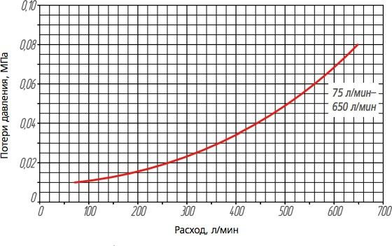 Hydraulic loss graphs for DS-65
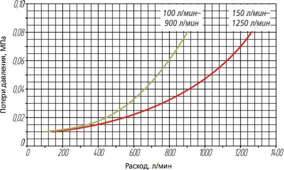 Hydraulic loss graphs for DS-80
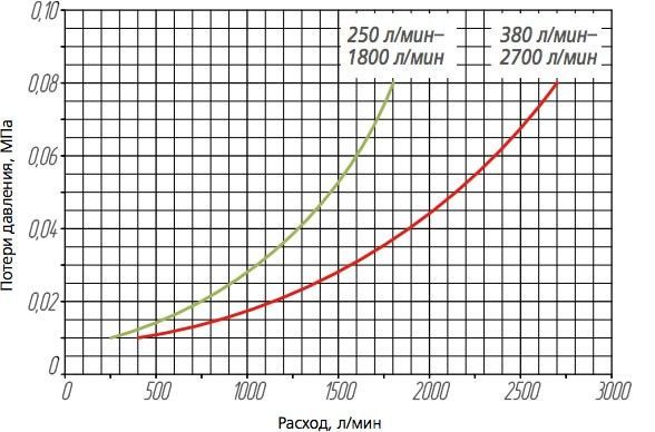 Hydraulic loss graphs for DS-100
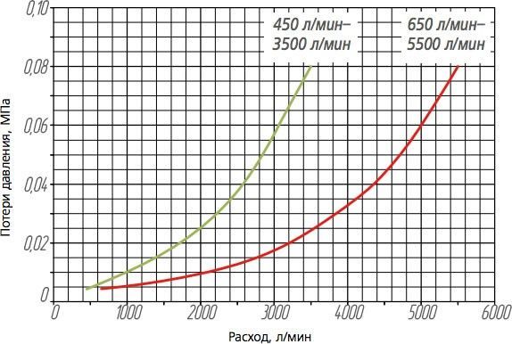 Hydraulic loss graphs for DS-150
 Hydraulic loss graphs for DS-200
 Hydraulic loss graphs for DS-250
Specifications for a wide range proportioner (DShD)
Nominal diameter, mm (inch) 100 (4") |
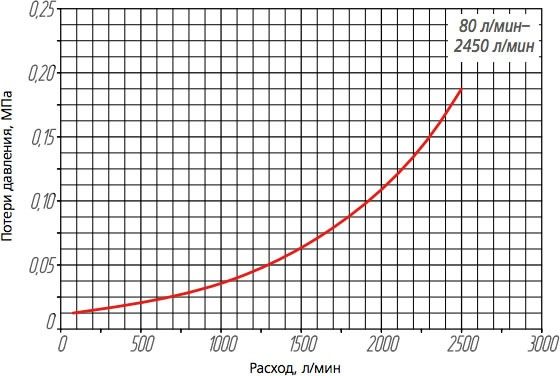
Foam concentrate solution flow rate, min-max, l/min 80–2450 |
Proportioning ratio 1 %, 3 %, 6 % |
Nominal diameter, mm (inch) 150 (6") |
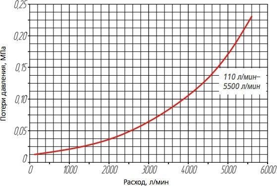
Foam concentrate solution flow rate, min-max, l/min 110–5500 |
Proportioning ratio 1 %, 3 %, 6 % |
Nominal diameter, mm (inch) 200 (8") |
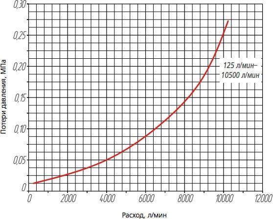
Foam concentrate solution flow rate, min-max, l/min 125–10500 |
Proportioning ratio 1 %, 3 %, 6 % |
Nominal diameter, mm (inch) 250 (10") |
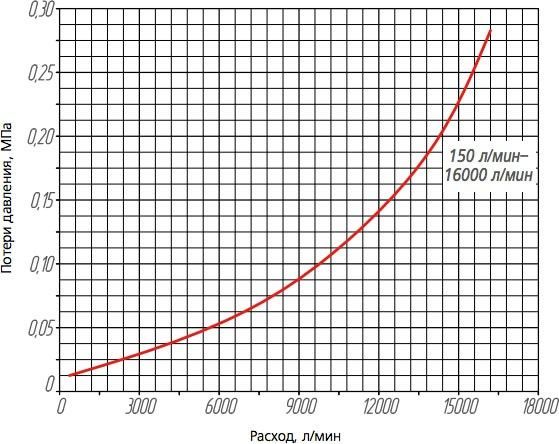
Foam concentrate solution flow rate, min-max, l/min 150–16000 |
Proportioning ratio 1 %, 3 %, 6 % |
| Indicator name | Indicator value | |||
| DShD-100 | DShD-150 | DShD-200 | DShD-250 | |
| Nominal diameter, mm (inch) | 100 (4") | 150 (6") | 200 (8") | 250 (10") |
| Foam concentrate solution flow rate, min-max, l/min | 80–2450 | 110–5500 | 125–10500 | 150–16000 |
| Foam concentrate Proportioning ratio | 1 %, 3 %, 6 % | |||
Optionally, proportioners can be manufactured with the insertion rate of 0.5% and with other flow rates.
The main elements and overall dimensions of DShD proportioners
1 – flange to feed water fr om the main line to the proportioner;
2 – flange to drain water to the foam concentrate tank;
3 – flange to feed foam concentrate fr om the tank to the proportioner;
4 – flange to drain foam concentrate solution fr om the proportioner;
5 and 6 – drain valves;
7 and 8 – pressure gauges.
Size, mm (inch) 100 (4") |
Type of flanges in accordance with GOST 33259-2015 100-16-01-1 |
Type of flanges in accordance with GOST 33259-2015 50-16-01-1 |
A, mm 295 |
B, mm 200 |
Weight, kg 65 |
Size, mm (inch) 150 (6") |
Type of flanges in accordance with GOST 33259-2015 150-16-01-1 |
Type of flanges in accordance with GOST 33259-2015 50-16-01-1 |
A, mm 320 |
B, mm 200 |
Weight, kg 95 |
Size, mm (inch) 200 (8") |
Type of flanges in accordance with GOST 33259-2015 200-16-01-1 |
Type of flanges in accordance with GOST 33259-2015 80-16-01-1 |
A, mm 350 |
B, mm 210 |
Weight, kg 140 |
Size, mm (inch) 250 (10") |
Type of flanges in accordance with GOST 33259-2015 250-16-01-1 |
Type of flanges in accordance with GOST 33259-2015 80-16-01-1 |
A, mm 380 |
B, mm 230 |
Weight, kg 170 |
| Indicator name | Indicator value | |||
| DShD-100 | DShD-150 | DShD-200 | DShD-250 | |
| Size, mm (inch) | 100 (4") | 150 (6") | 200 (8") | 250 (10") |
| Type of flanges in accordance with GOST 33259-2015 (pos. 1 and 4 on figure) | 100-16-01-1 | 150-16-01-1 | 200-16-01-1 | 250-16-01-1 |
| Type of flanges in accordance with GOST 33259-2015 (pos. 2 and 3 on figure) | 50-16-01-1 | 50-16-01-1 | 80-16-01-1 | 80-16-01-1 |
| A, mm | 295 | 320 | 350 | 380 |
| B, mm | 200 | 200 | 210 | 230 |
| Weight, kg | 65 | 95 | 140 | 170 |
Hydraulic Loss Graphs for DShD Proportioners
To compare two graphs, select both values.
 Hydraulic loss graphs for DShD-100
 Hydraulic loss graphs for DShD-150
 Hydraulic loss graphs for DShD-200
 Hydraulic loss graphs for DShD-250
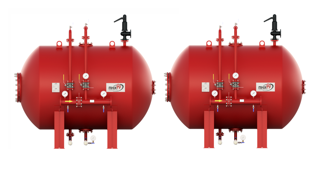
Component parts list for Antifire bladder tank base case
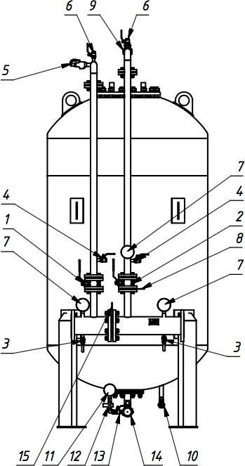
1 – shut-off valve on water feed pipeline to the tank;
2 – shut-off valve on foam concentrate feed pipeline to the proportioner;
3 – proportioner drainage valve;
4 – pressure relief valve;
5 – safety valve;
6 – system air removal valve;
7 – pressure gauge;
8 – calibrated diaphragm on the foam concentrate line;
9 – check valve;
10 – tank drainage valve;
11 – flow meter;
12 – safety valve (valve block);
13 – shut-off valve;
14 – flexible storage container drainage valve;
15 – proportioner calibrated diaphragm;
16 – flexible container (located inside the tank);
17 – perforated piping (located inside the tank)..
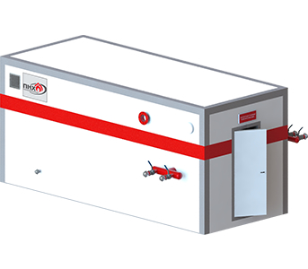
Optionally, the product can be supplied with additional equipment.
Для просмотра полного описания технических характеристик отправьте заявку или войдите под своим профилемArticles
Bladder tank. Purchase, installation and operation of a bladder tank at a production site
Bladder tank as a foam concentrate storage and dosing system common on the Russian market.
Bladder tank. How to reduce risks when purchasing and operating a bladder tank?
Bladder tanks have been widely used in domestic fire extinguishing installations since the early 2000s.
Instructions for choosing a bladder tank for the purchasing department (pdf, 7.2 Mb)